Card connector

a card connector and connector technology, applied in the direction of coupling device connection, instruments, computing, etc., can solve the problems of card connectors becoming larger in size, breakage of the same, and breakage of the same, and achieve the effect of strengthening the structur

Inactive Publication Date: 2005-01-11
YAMAICHI ELECTRONICS
View PDF5 Cites 48 Cited by
  • Summary
  • Abstract
  • Description
  • Claims
  • Application Information

AI Technical Summary

Benefits of technology

To achieve the above-mentioned object, a card connector of the present invention comprises a base and a sheet metal cover to be combined therewith to form a flat hollow housing, wherein a plurality of pin-like elongate terminal members are provided in the sheet metal cover so as to extend from an end and side walls of the sheet metal cover, so that the base and the sheet metal cover are integral with each other to have a strengthened structure durable against the falling impact as well as low in height as the market has required.

Problems solved by technology

If the housing from which the antenna is projected out is unintentionally fell down and the card collides with a concrete portion, a very large impact is applied to the card connector to often cause a breakage of the same.
However, if such a card connector slips from a hand, a large impact is applied thereto to cause a breakage of the same.
Further, if reinforcing the card connector to strengthen the same, there may be a problem in that the card connector becomes larger in size to increase a height thereof.

Method used


Image

  • Card connector
  • Card connector
  • Card connector

Examples


Embodiment Construction

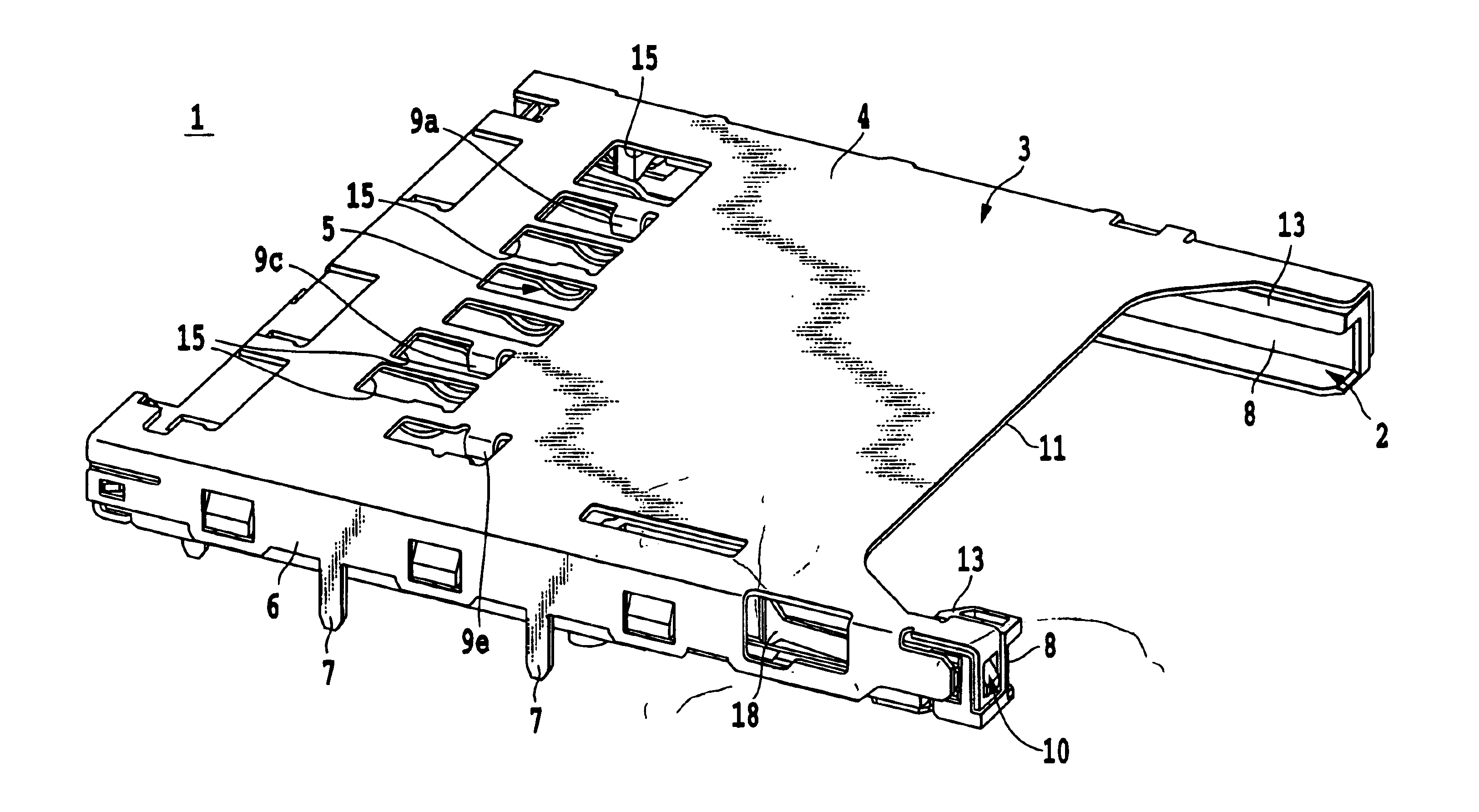
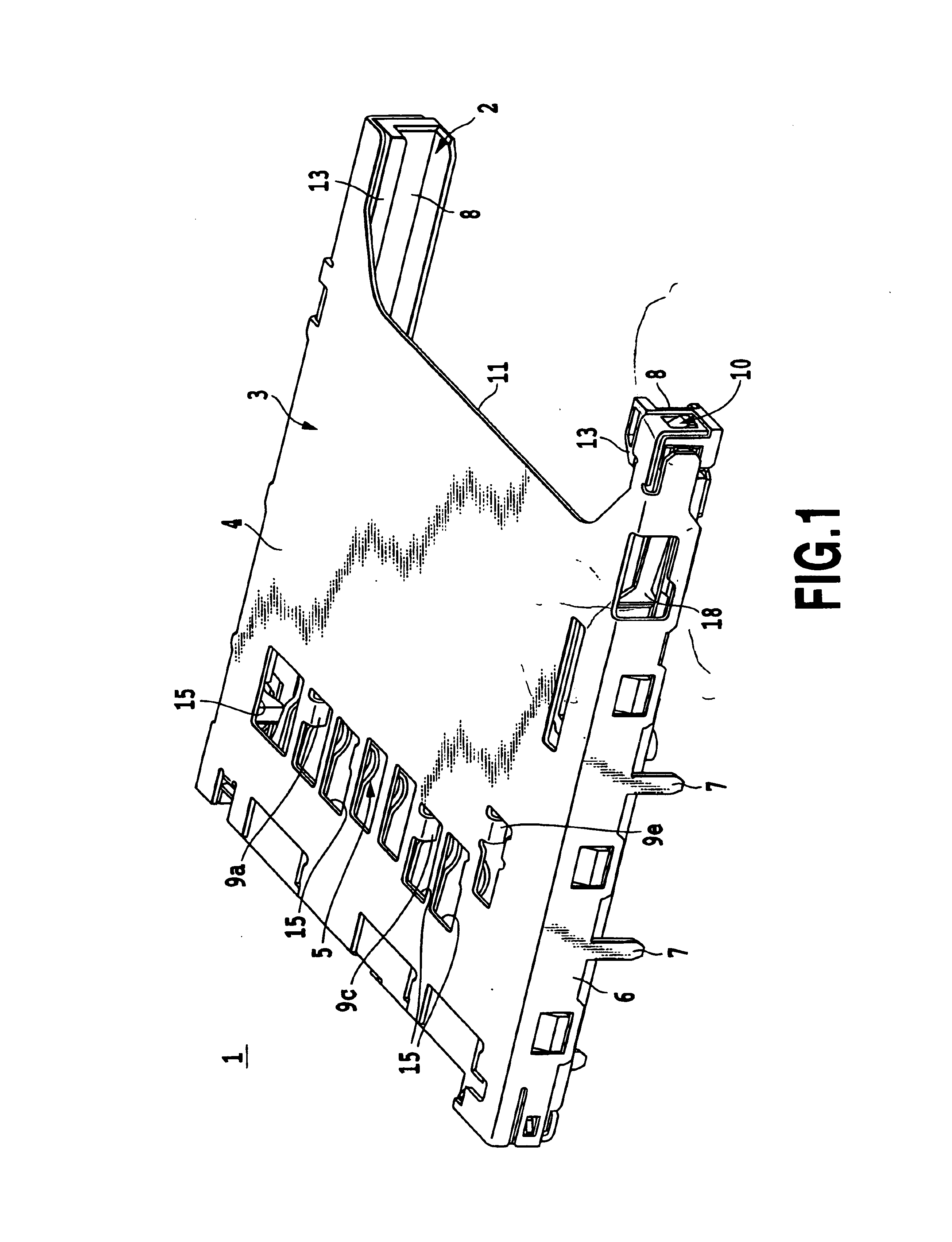
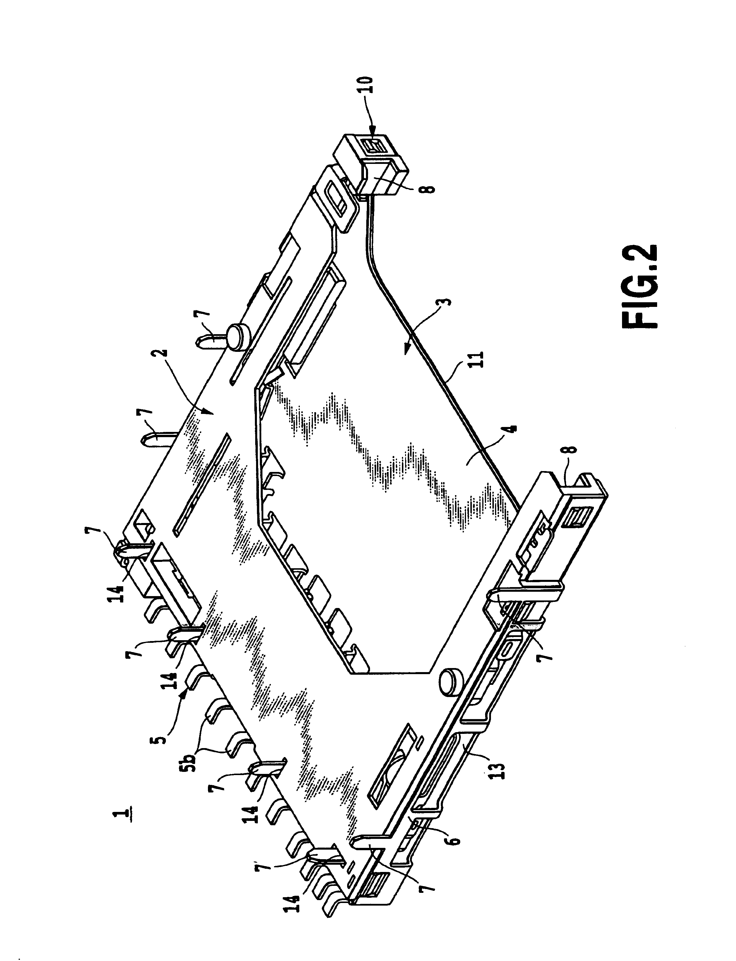
FIGS. 1 to 7 illustrate an embodiment of a card connector according to the present invention, wherein FIG. 1 is a perspective view of a card connector according to the present invention, FIG. 2 is a perspective view of the card connector according to the present invention shown in FIG. 1 as seen from the back side, FIG. 3 is a perspective view of the card connector shown in FIG. 1, disassembled into a base and a metal sheet cover, FIG. 4 is a perspective view of the card connector shown in FIG. 3, disassembled into the base and the metal sheet cover, as seen from the back side, FIG. 5 is a partial perspective view of connector terminal portions when the base and the metal sheet cover of the card connector are assembled to each other, FIG. 6 is a perspective view showing a state before a printed circuit board is mounted to the card connector according to the present invention, and FIG. 7 is a perspective view showing a state after the printed circuit board is mounted to the card conn...


PUM


Abstract

A card connector including a base and a sheet metal cover combined with the base to form a flat hollow housing. Also, a plurality of pin-like elongate terminal members extend from an end and lateral walls of the sheet metal cover to be integral with the base, whereby a structure durable against an impact imposed when the housing falls is obtainable as well as the height of the card connector becomes smaller as the market requires.

Description

This application is based on patent application No. 2001-303471 filed on Sep. 28, 2001 in Japan, the content of which is incorporated herein by reference.BACKGROUND OF THE INVENTION1. Field of the InventionThe present invention relates to a card connector attached to an electronics apparatus or an information terminal device such as a portable phone, a telephone, PDA (personal digital assistance), a portable audio or a camera, particularly to a card connector in which a card such as an IC card, SD card or SIM card is to be inserted.2. Description of the Related ArtRecently, in an electronics apparatus or an information terminal device such as a portable phone, a telephone, PDA (personal digital assistance), a portable audio or a camera, an IC card, SD card or SIM card in which an IC part called as an IC chip is incorporated has been increasingly used, and therefore a card connector for inserting such the IC card, SD card or SIM card has been widely required.Also, there is a card elo...

Claims


Application Information

Patent Timeline
Patent Type & Authority Patents(United States)
IPC IPC(8): H01R12/16H01R12/00G06K17/00
CPCH01R23/6873H01R13/6594H01R12/00
Inventor OOYA, MASAAKIABE, KIYOSHIONO, YASUHIRO
Owner YAMAICHI ELECTRONICS
Why Eureka
Try Eureka