Endoscopic instrument system having reduced backlash control wire action

a control wire and endoscope technology, applied in the field of surgical instruments, can solve the problems of difficult to achieve difficulty in overcoming problems such as backlash (lost motion) experienced by the doctor, and difficulty in achieving this level of accuracy, and achieve the effect of little or no backlash

Inactive Publication Date: 2005-01-11
SCI MED LIFE SYST
View PDF172 Cites 33 Cited by
  • Summary
  • Abstract
  • Description
  • Claims
  • Application Information

AI Technical Summary

Benefits of technology

The present invention provides an endoscopic system with little or no backlash, or lag, when manipulating an outer tube of an endoscopic instrument relative to an endoscope working channel and / or a control member of the instrument relative to the outer tube containing such control member, while maintaining an open area therebetween for permitting fluid flow and / or relative movement without excessive friction.

Problems solved by technology

However, because of friction and backlash in the way the instrument passes through the endoscope, achieving this level of accuracy is difficult.
As a result, quite a bit of backlash (lost motion) is experienced by the doctor when the doctor tries to manipulate the distal end of the instrument.
However, this is not a simple problem to overcome for several reasons.
However, this is not a practical solution, because it is often necessary to inject fluid (or to operate suction) through the annular space between these two structures.
This increase in contact area between these parts results in an increase in frictional drag on the control member when the doctor attempts to move it relative to the tubular shaft.

Method used


Image

  • Endoscopic instrument system having reduced backlash control wire action
  • Endoscopic instrument system having reduced backlash control wire action
  • Endoscopic instrument system having reduced backlash control wire action

Examples


first embodiment

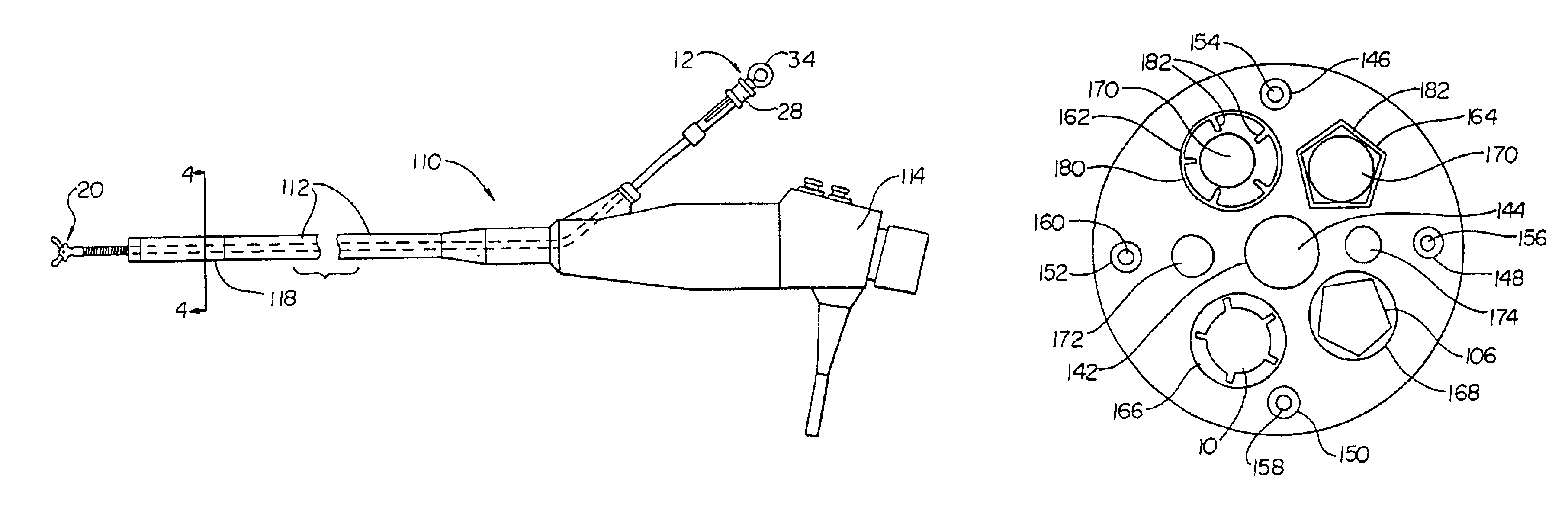
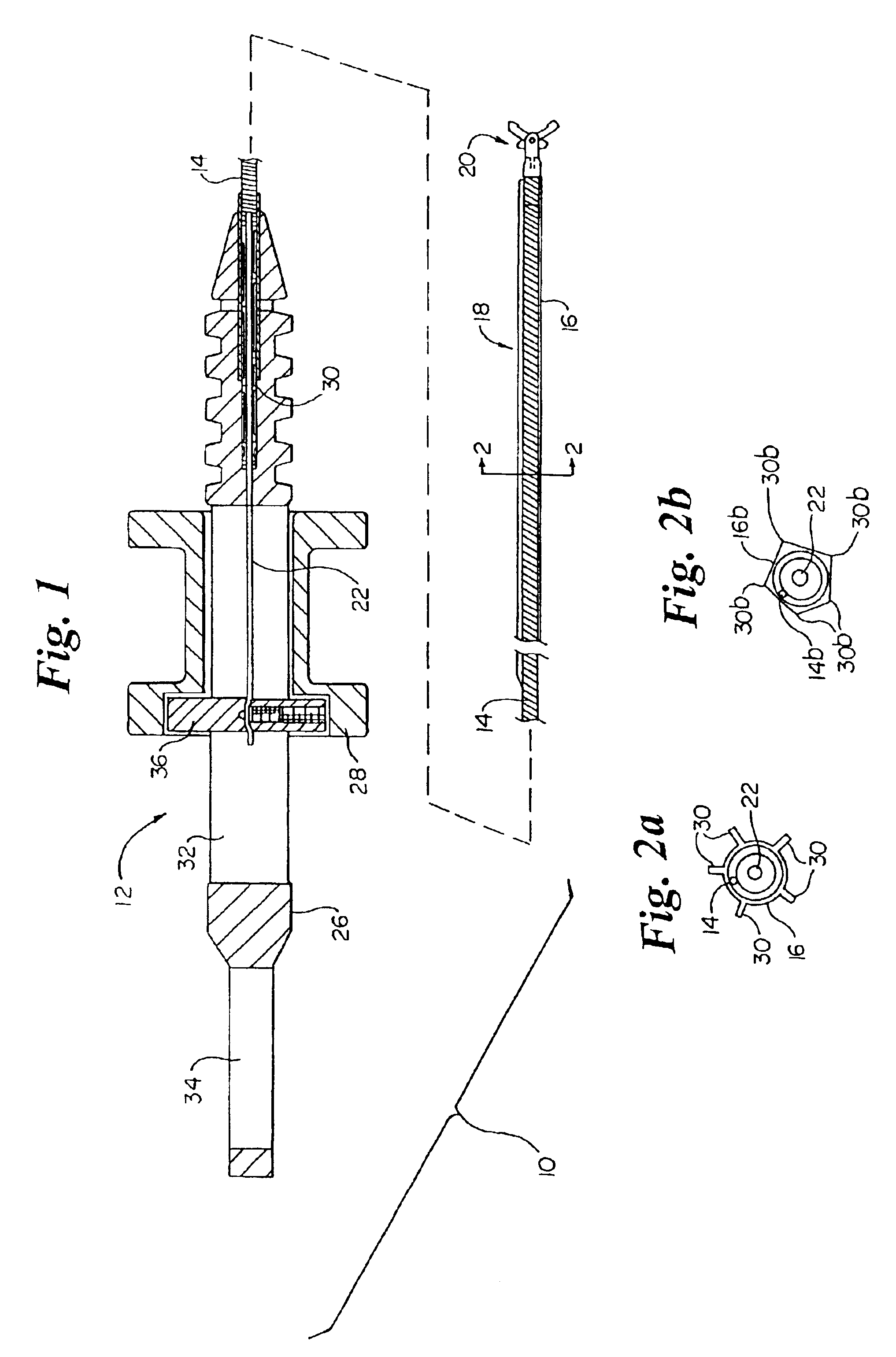
Turning now to FIG. 1, an endoscopic instrument 10 for insertion through a working channel of an endoscope is shown. According to the invention, the endoscopic instrument 10 includes an actuation handle 12, a tubular coil 14, a jacket 16 provided about at least a distal portion 18 of the coil 14, an end effector assembly 20, e.g., a biopsy forceps, and a control wire 22. The actuation handle 12 typically includes a stationary member 26 and a displaceable spool 28. The stationary member 26 includes a distal throughbore 30, a central slot 32, and a proximal thumb ring 34. The displaceable spool 28 is slidably disposed on the stationary member 26 and has a cross member 36 which passes through the slot 32. The proximal end of the control wire 22 is coupled to the spool 28. Operation of the actuation handle 12 is described fully in U.S. Pat. No. 5,228,451 to Bales, which is hereby incorporated by reference herein in its entirety. In brief, longitudinal movement of the spool 28 within the...

second embodiment

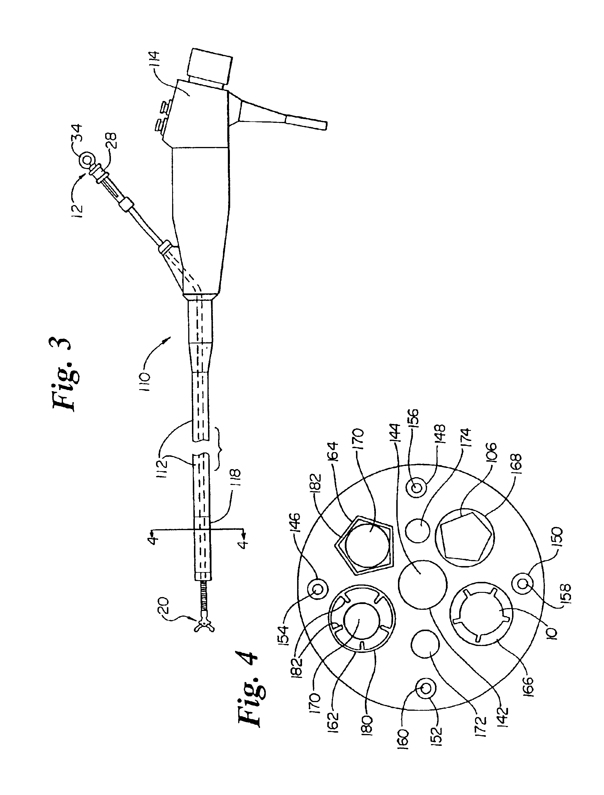
According to the invention, a portion of at least one of the working channels 162 is provided with a non-circular cross-sectional shape. The noncircular cross-sectional shape may be molded into the working channel or more preferably is provided by a low-friction (e.g., PTFE) insert 180 preferably fixed within a distal portion 118 of the working channel 162. The insert 180 includes a plurality of radially spaced and radially inwardly directed longitudinal ribs 182. The ribs 182 can be quite small. For example, the ribs 182 may be approximately 0.1 mm thick and have a radial length of approximately 0.5 mm. Therefore, the ribs would have a minimal effect on the fluid flow cross-sectional area between the working channel and the endoscopic instrument, and also provide relatively small contact points between the working channel and the endoscopic instrument.

According to an alternate second embodiment of the invention, a working channel 164 is provided with a polygonal cross-sectional sha...


PUM


Abstract

An endoscopic instrument has a control member, a portion of the member having an outer surface with a non-circular cross-sectional shape. The non-circular cross-sectional shape may be provided to the control member by providing peripheral projections or fins along the length of the portion or by providing the periphery of the portion with a polygonal shape. Where fins are used, the fins are preferably quite small and only have a minimal effect on the fluid flow cross-sectional area between the interior of the endoscope instrument shaft and the central control member. The resulting instrument has significantly reduced backlash in end effector assembly manipulation, while maintaining adequate fluid flow in the endoscope shaft. According to a second embodiment of the invention, a portion of the interior of the shaft of the endoscopic instrument has an interior surface having a non-circular cross-sectional shape by the inclusion of a plurality of radially spaced and inwardly directed ribs or by being polygonally shaped. The resulting endoscopic instrument likewise reduces the backlash experienced in operating the distal end effector assembly.

Description

FIELD OF THE INVENTIONThis invention relates broadly to surgical instruments. More particularly, this invention relates to an endoscope and endoscopic surgical instruments adapted to be extended into a channel of the endoscope.BACKGROUND OF THE INVENTIONAt the present time there are many instruments made for use in endoscopic medical procedures. Typically, endoscopic instruments are long and flexible cylindrically tubular devices with manually operated handles at their proximal ends and tissue-manipulative cutting, grasping, injecting, or cauterizing components at their distal ends. These distal devices, also called effector-end assemblies, after being moved to the intended treatment site by means of the endoscopic instrument tube, are operated by a control member, such as a wire. The control member typically may be pushed as well as pulled, to allow motion of the control element, and therefore operation of the distal device, in both directions. For example, the control member may a...

Claims


Application Information

Patent Timeline
Patent Type & Authority Patents(United States)
IPC IPC(8): A61B1/015A61B1/012A61B1/018A61B1/00G02B23/24A61B17/28
CPCA61B1/018A61B1/015
Inventor SMITH, KEVIN W.
Owner SCI MED LIFE SYST
Why Eureka
Try Eureka