
System and method for tuning step coverage gap correction in a scan strategy

a scanning strategy and step coverage technology, applied in diversity/multi-antenna systems, instruments, reradiation, etc., can solve problems such as the inability of receivers to observe all threats at all frequencies simultaneously, the number of resources, and the inability to detect all threats at the same tim

Inactive Publication Date: 2005-01-11
LOCKHEED MARTIN CORP
View PDF28 Cites 15 Cited by
  • Summary
  • Abstract
  • Description
  • Claims
  • Application Information

AI Technical Summary

Benefits of technology

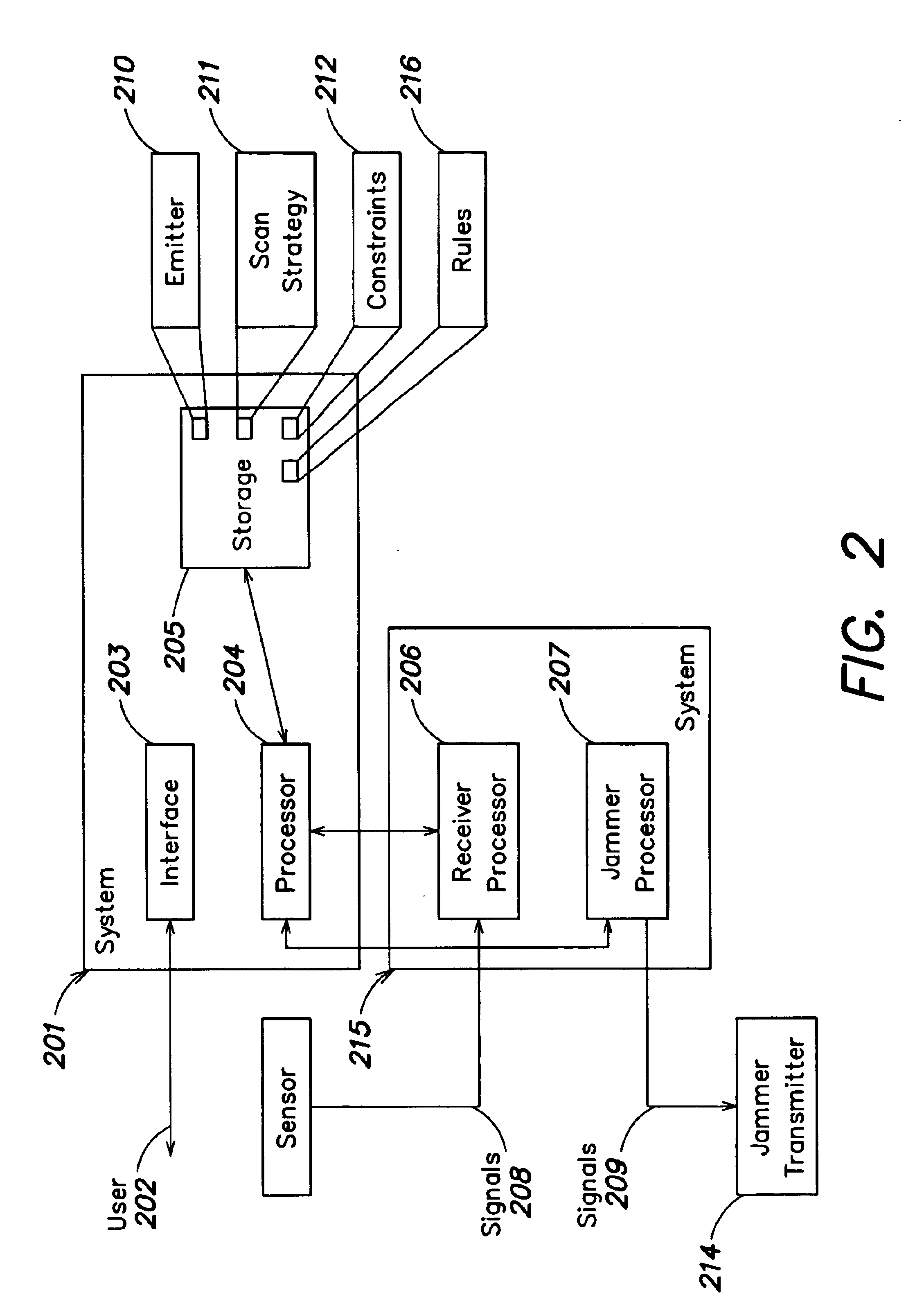
The invention provides a method and system for detecting emitter signals using a receiver with a tuning step size. The method involves creating a first dwell to detect a set of emitters, shifting the frequency range of the first dwell to generate a second frequency range if the first minimum frequency is not an integer multiple of the tuning step size. The system includes a memory with a scan strategy created by a system that performs these acts. The technical effect of the invention is improved detection of emitter signals with greater accuracy and efficiency.

Problems solved by technology

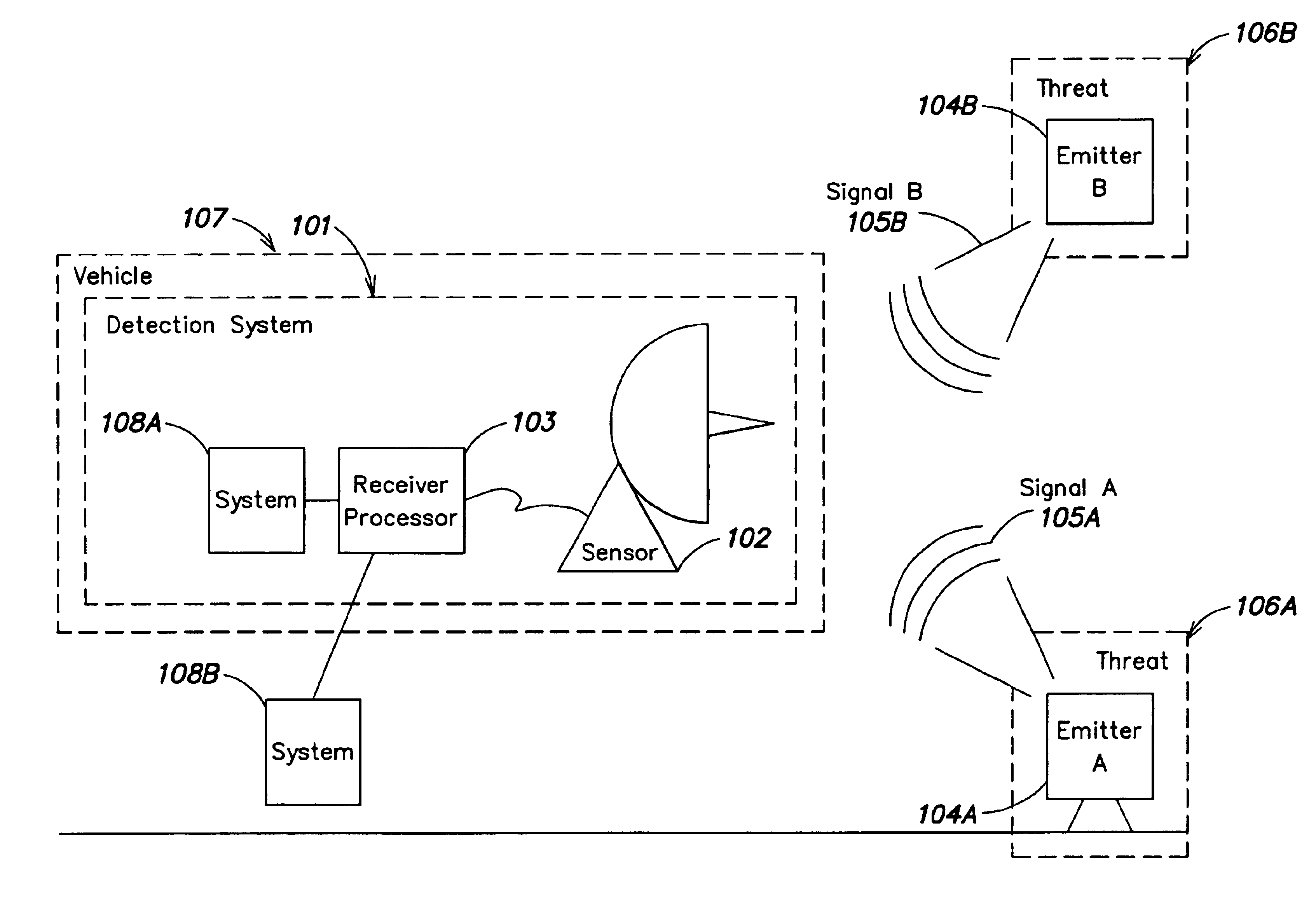
There is a problem in that there may be multiple threats but only a finite number of resources to detect them.
More particularly, there may be hundreds of threats, but receiver capabilities do not allow all threats to be observed simultaneously at all frequencies.
There is difficulty in balancing the need for detecting each of numerous possible threats because of the finite resources of the detection system.
That is, hardware and / or software (e.g., memory, processing capability, etc.) of the detection system may be limited to monitor only certain portions of the frequency spectrum of interest or may be limited to detecting a limited number of threats.
Practically, there are a number of threats that are concurrently transmitting that should be detected, but it is expensive from a hardware standpoint to monitor all frequencies of interest at all times to detect all threats simultaneously.

Method used


Image

  • System and method for tuning step coverage gap correction in a scan strategy
  • System and method for tuning step coverage gap correction in a scan strategy
  • System and method for tuning step coverage gap correction in a scan strategy

Examples


examples

The POP Boolean control is either on or off, so conflicts are handled by sorting dwells around the conflict, or if that is not possible, flagging the conflict.

This is illustrated by the following example:

Emitter #1 Frequency range: 1500-2000 MHz, POP On (normal case). Emitter #2 Frequency range: 2050-2550 MHz. POP Off (for some receivers, this is required for AM pulses, since the assumption of “square” pulses is not true, and may cause multiple encoding if POP is left enabled).

Assume a detecting bandwidth of 1000 MHz and 250 MHz. Any solution that attempts to include the emitters in the same dwell will cause a conflict to be detected. Such solutions are not favored by the dwell placement methods described below, which should find at least two 1000 MHz dwells at bandwidths 1000-2000 and 2050-3050. These two dwells avoid the conflict. If there is no gap between the dwells, or if additional conflict exists, then the 1000 MHz dwell may not be allowed.

For instance, expanding on the previ...


PUM


Abstract

A system and method is provided for detecting emitter signals and for determining a scan strategy for a receiver system that receives such emitter signals. If a dwells assigned frequency bandwidth is small and not a multiple of the minimum frequency spacing between dwells (tuning step), then coverage gaps can be inadvertently introduced between adjacent dwells. A system and method are provided for detecting this condition and generating dwells without accidental loss of frequency coverage for any combination of bandwidth and step size.

Description

FIELD OF THE INVENTIONThe invention generally relates to signal detection, and more particularly, to detecting and analyzing signals generated by emitters.BACKGROUND OF THE INVENTIONDetection systems exist for detecting signals generated by emitters which are of interest. For example, there are scanners (e.g., a police scanner) that are capable of scanning a frequency band for transmissions within that frequency band. In the case of a police scanner, channels are scanned sequentially to find a signal of interest. Scanning is achieved by tuning receiver hardware to a particular frequency to observe one or more transmissions within that particular frequency.There are more sophisticated systems to detect transmitted signals that use other methods for determining signals of interest. For instance, there are what are referred to as Electronic Support Measures / Electronic Intelligence (ESM / ELINT) systems for conducting surveillance (e.g., radar, and other signals across a wide range of fre...

Claims


Application Information

Patent Timeline
Patent Type & Authority Patents(United States)
IPC IPC(8): G01S7/02
CPCG01S7/021
Inventor GOUNALIS, ANTHONY J.
Owner LOCKHEED MARTIN CORP
Learn More