Microphone mount

Inactive Publication Date: 2005-01-11
KUERTI RANDY H +1
View PDF10 Cites 22 Cited by
  • Summary
  • Abstract
  • Description
  • Claims
  • Application Information

AI Technical Summary

Benefits of technology

In one of the alternative embodiments, the support member may be telescoped to an appropriate length for a given speaker size to accurately adjust the position of the microphone to the desired acoustic zone of the speaker. Also, the angle

Problems solved by technology

For amplified instruments, such as electric guitars, electric basses, and other electric instruments, there is considerable difficulty in capturing the sound from a guitar amp to be inputted into a P.A. system.
A microphone was held, unconnected to the speaker cabinet, so the head of the mike was within the “cube.” However, either movement of the stand or movement of the speaker cabinet would remove the microphone from the cube and the audio signal from the speaker would not be applicabl

Method used


Image

  • Microphone mount
  • Microphone mount
  • Microphone mount

Examples


Example

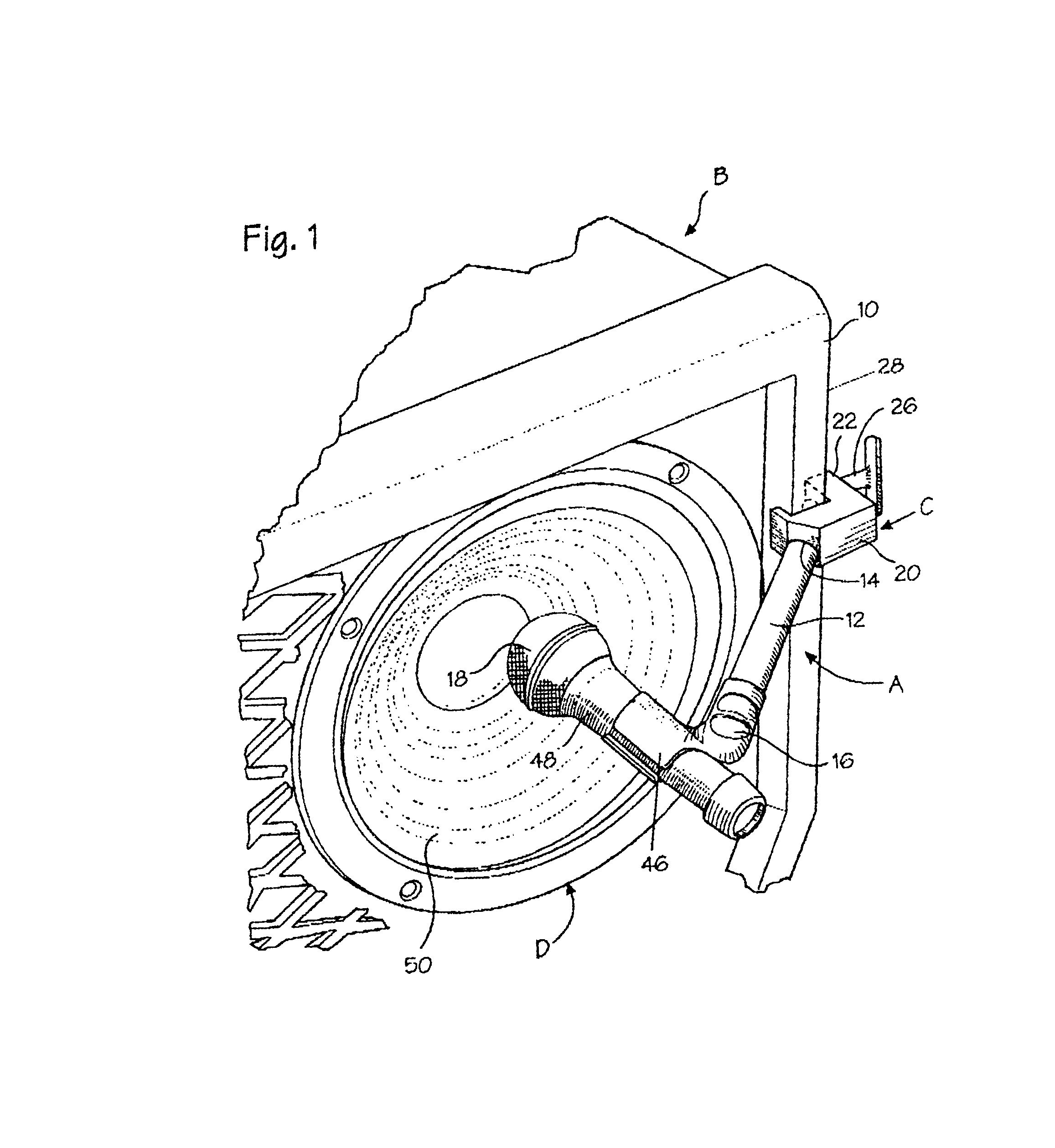
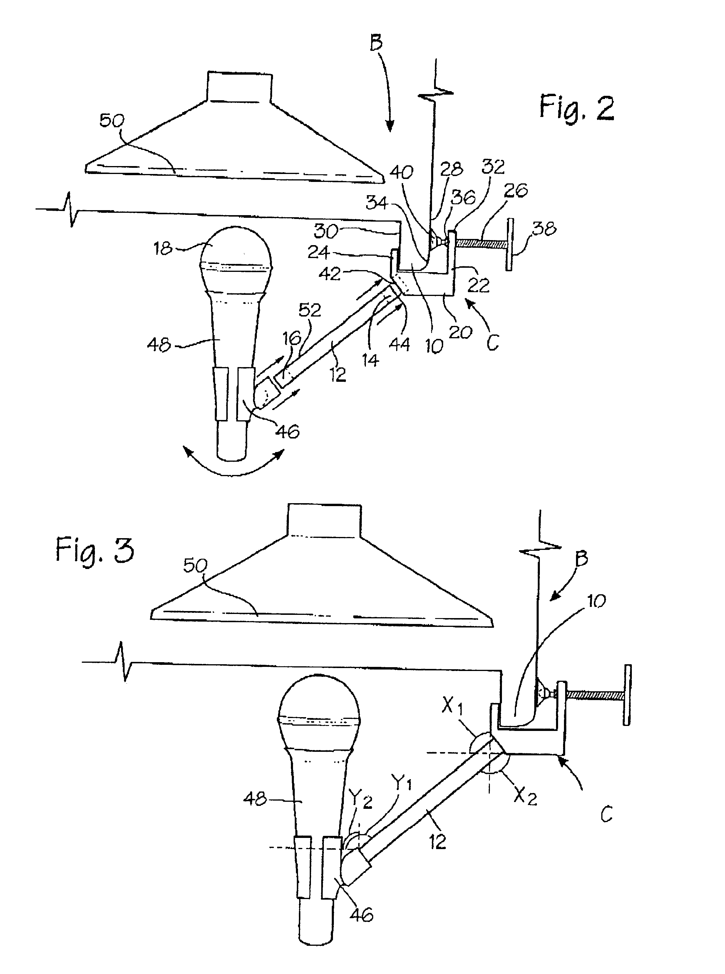
Referring now to the drawings, the invention will be described in more detail. Referring to FIGS. 1 and 2, the preferred embodiment of the microphone mount, shown generally as A, is shown attached to a rim 10 of a speaker cabinet B. Microphone mount A comprises an elongated support member 12 with a first end 14 affixed to the speaker cabinet B and a second distal end 16 carrying a microphone 18 at a desired acoustic zone for receiving sound emanated from a speaker D.

Typically, a speaker cabinet has rim 10 which surrounds the front of the speaker cabinet on which the microphone mount may be attached. In the preferred embodiment, microphone mount A has an attachment member C which affixes the first end 14 of the elongated support member to the rim of the speaker cabinet. The attachment member is generally a U-shaped frame 20, having a first leg 22 and a second leg 24. The rim 10 of the speaker cabinet is received between the first and second legs. The first leg 22 extends along the ou...


PUM


Abstract

An amplified sound system wherein a microphone is maintained at a desired acoustic zone in front of a speaker for enhancing performance in receiving sound emanated from said speaker. The system comprises a speaker cabinet containing at least one speaker, a microphone mount and a microphone for receiving sound emanated from said speaker. The microphone mount has an elongated support member for supporting said microphone at a desired spacial distance in front of the speaker. The support member has a first end attached to the speaker cabinet, and a second end on which the microphone is carried so that the microphone is positioned in a desired acoustic zone for collecting sound emanated from said speaker.

Description

FIELD OF THE INVENTIONThis invention is directed to a speaker cabinet with a microphone mount, more specifically, to a mount for securing a microphone to a speaker cabinet so that the microphone is held in front of a speaker's desired acoustic zone, advantageously, to capture the optimum sound emanated from the speaker.BACKGROUND OF THE INVENTIONSince the advent of sound amplification, musicians have been using amplifiers and speakers in order to project their performances to greater areas. The public address (P.A.) system has been instrumental in providing this functionality. Using the P.A. system for performances, a mixing board controls the audio signal inputted to the amplifiers, as well as the signals outputted to the speakers. For amplified instruments, such as electric guitars, electric basses, and other electric instruments, there is considerable difficulty in capturing the sound from a guitar amp to be inputted into a P.A. system. Usually, a guitar amplifier will have at le...

Claims


Application Information

Patent Timeline
IPC IPC(8): H04R3/00
CPCH04R3/002
Inventor KUERTI, RANDY H.COLE, GREGORY A.
Owner KUERTI RANDY H
Why Eureka
Try Eureka