Prediction parameter analysis apparatus and a prediction parameter analysis method

a prediction parameter and analysis method technology, applied in the field of prediction parameter analysis apparatus or prediction parameter analysis method, can solve the problems of inaccurate prediction parameters, unfavorable prediction parameters, and difficulty in obtaining prediction parameters stably, and achieve the effect of high analysis efficiency

Inactive Publication Date: 2005-01-11
KK TOSHIBA
View PDF12 Cites 4 Cited by
  • Summary
  • Abstract
  • Description
  • Claims
  • Application Information

AI Technical Summary

Benefits of technology

It is an object of the present invention to provide a prediction parameter analysis apparatus and a prediction parameter method having a high analysis efficiency and can keep mixture of an unnecessary component to a minimum.

Problems solved by technology

Such an unnecessary component increases in case of prediction analysis using the short time window particularly.
The unnecessary component affects the analysis of prediction parameters due to tendency to deviate to a low frequency band, resulting in incorrect prediction parameters.
For the above reasons, the conventional prediction parameter analysis includes a problem that it is difficult to obtain the prediction parameters stably.
Therefore, the undesired prediction parameters occur.

Method used


Image

  • Prediction parameter analysis apparatus and a prediction parameter analysis method
  • Prediction parameter analysis apparatus and a prediction parameter analysis method
  • Prediction parameter analysis apparatus and a prediction parameter analysis method

Examples


first embodiment

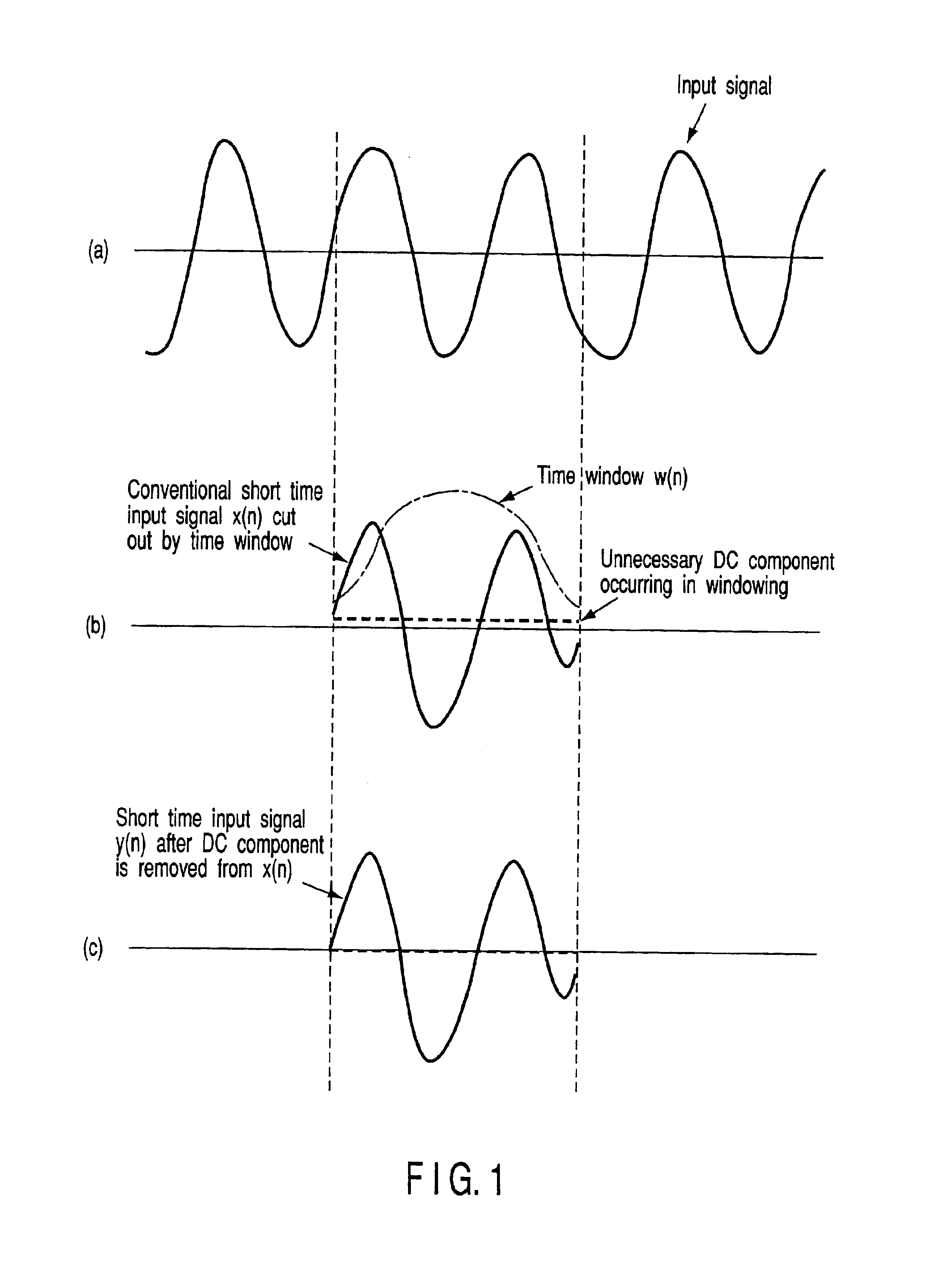
FIG. 1 shows a waveform for explaining a principle of prediction parameter analysis based on the present invention.

A waveform (a) represents a waveform of an input signal input to a prediction parameter analysis apparatus. The input signal is a signal that the unnecessary low frequency component affecting a prediction parameter analysis is removed from an actual input signal in preprocessing. The preprocessing is realized using a high pass filter with a cutoff frequency of around 50-100 Hz typically. The input signal (shown by (a) in FIG. 1) from which the unnecessary component is removed is cut out by windowing in units of a given length (10 msec to 20 msec). In other words, the input signal is windowed by a time window w (n), to be cut out as a short time input signal x(n) (shown by (b) in FIG. 1). In this case, the input signal is windowed so that harmful effect affecting the frames on both ends of the extracted frame is decreased. As one example, a Humming window or a hybrid win...

second embodiment

(The Second Embodiment)

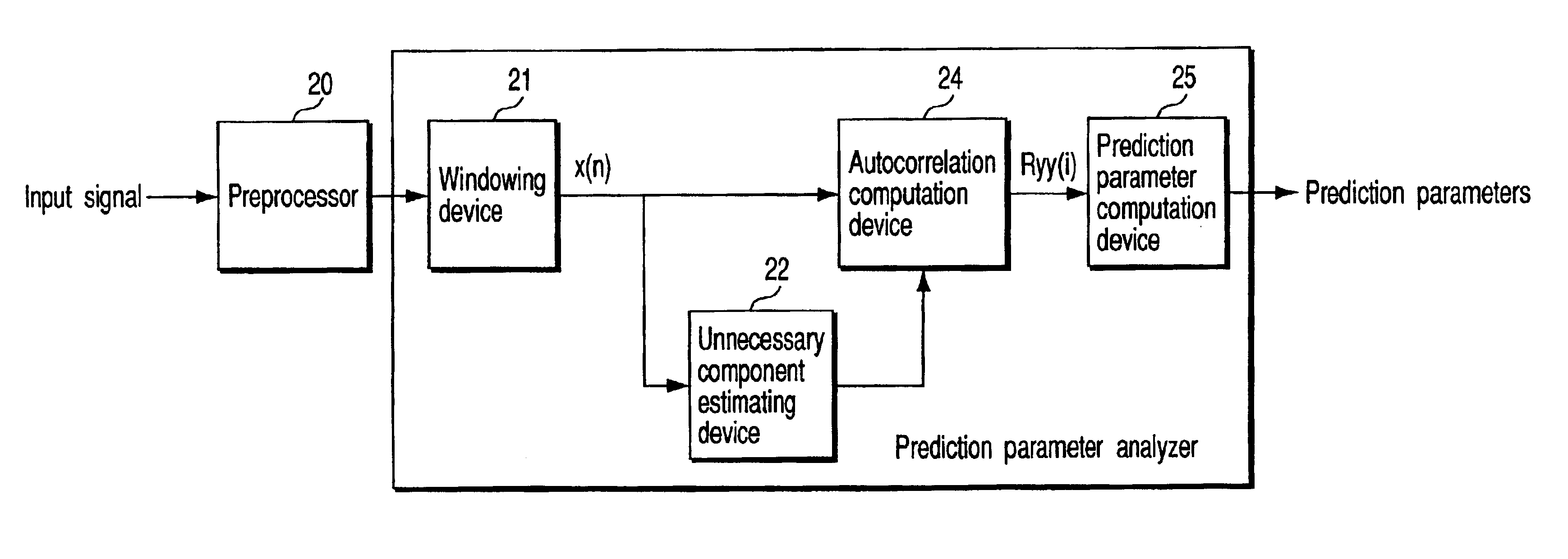
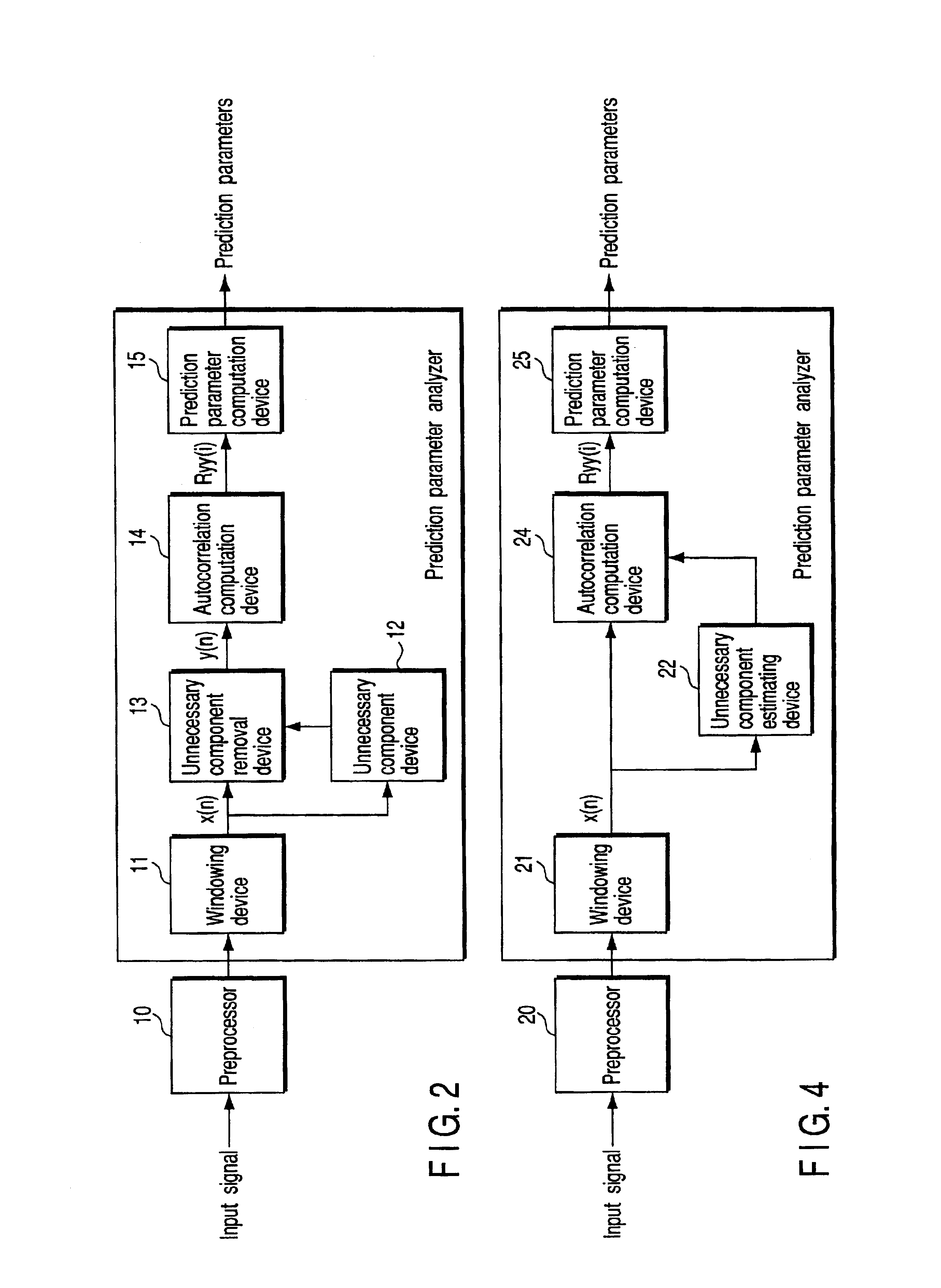
In the first embodiment, the DC component is directly removed from the short time input signal. In the second embodiment, the affection due to the DC component is excluded in a level of the autocorrelation. FIG. 4 shows a prediction parameter analysis apparatus related to the second embodiment. According to this, the preprocessor 20 preprocesses the input signal similarly to the first embodiment, and input the preprocessed input signal to a widowing device 21. The windowing device 21 cuts out a short time input signal by subjecting the preprocessed signal to windowing. The unnecessary component estimation device 22 analyzes an unnecessary component included in the short time input signal x(n), to generate an estimation signal, and outputs it to an autocorrelation computation device 24. The short time input signal x(n) is sent to the autocorrelation calculation device 24, too. For example, in the short time input signal input to the autocorrelation computation ...

third embodiment

(The Third Embodiment)

FIG. 6 shows a prediction parameter analysis apparatus of the third embodiment. According to the third embodiment, a prediction parameter analysis device comprises a short time input signal generator 41 which generates a short time input signal from an input signal or a signal deriving from the input signal, a component removal device 43 which remove DC components or predetermined frequency band components from the short time input signal, an autocorrelation computation device 44 which computes autocorrelation coefficients based on a modified short time input signal provided from the component removal device 43, and a prediction parameter computation device 45 which computes prediction parameters based on the autocorrelation coefficients.

FIG. 7 shows a flowchart for explaining a prediction parameter analysis method of the third embodiment of the present invention. At first, an input signal is input to the short time input signal generator 41 of the prediction p...


PUM


Abstract

A prediction parameter analysis apparatus comprises a windowing part which generates a short time input signal by subjecting an input signal or a signal derived from the input signal to windowing, a component removal part which removes an unnecessary component from the short time input signal to generate a modified short time input signal, an autocorrelation coefficient computation part which computes autocorrelation coefficients based on the modified short time input signal, and a prediction parameter computation part which computes prediction parameters based on the autocorrelation coefficients.

Description

CROSS-REFERENCE TO RELATED APPLICATIONSThis application is based upon and claims the benefit of priority from the prior Japanese Patent Application No. 2001-149564, filed May 18, 2001, the entire contents of which are incorporated herein by reference.BACKGROUND OF THE INVENTION1. Field of the InventionThe present invention relates to a prediction parameter analysis apparatus or a prediction parameter analysis method to acquire prediction parameters from an input signal.2. Description of the Related ArtIn a field of audio encoding, LP parameters (linear prediction parameters) are used broadly as spectrum parameters used for expressing the envelope of a spectrum of a signal in speech coding and speech synthesis. An LP parameter analysis performed in the speech coding will be described as an example of prediction parameter analysis.The conventional prediction parameter analysis is performed as follows.At first, unnecessary low frequency components affecting analysis of prediction param...

Claims


Application Information

Patent Timeline
Patent Type & Authority Patents(United States)
IPC IPC(8): G10L11/00G10L21/0208G10L25/00G10L25/06G10L25/12G10L25/45H03M7/36H04B14/06
CPCG10L25/48G10L25/12
Inventor MISEKI, KIMIO
Owner KK TOSHIBA
Why Eureka
Try Eureka