Optical information processor and optical element
a technology of optical information processor and optical element, which is applied in the field of optical information processor, can solve the problems of reducing the margin for tilt and defocus, the inability to use the beam for recording purposes, and the reliability of the beam with a shorter wavelength than that, so as to achieve excellent recording and reproduction, the effect of not reducing the margin for defocus and til
- Summary
- Abstract
- Description
- Claims
- Application Information
AI Technical Summary
Benefits of technology
Problems solved by technology
Method used
Image
Examples
first embodiment
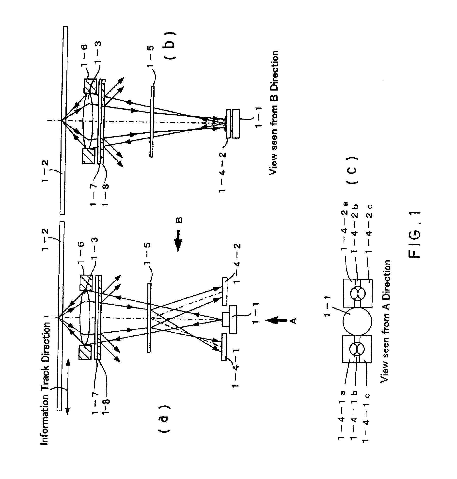
[0047]FIGS. 1(a), 1(b), and 1(c) show structural examples of an optical information processing method according to a first embodiment of the present invention. The description of the same points, such as a detection principle of FE, TE, RF signals as those in the conventional example, shown in FIGS. 18(a) and 18(b) is omitted. In the conventional example, the NA in an incoming path and the NA in a return path are determined by the objective lens holder 18-6 and are equal. In the present embodiment, an aperture is determined by an objective lens holder 1-6, a λ / 4 plate 1-7 that is a component of an aperture element, and a diffraction grating 1-8. The diffracting grating 1-8 is provided with a grating at the portion indicated with hatching in the figure.
[0048]The operation of the aperture element is described as follows. The λ / 4 plate 1-7 has a function of providing a phase difference of λ / 4 to incident light. The diffraction grating 1-8 is a grating having concave and convex portions...
second embodiment
[0056]FIGS. 4(a), 4(b), and 4(c) show structural examples according to a second embodiment of the present invention when the apertures in the incoming and return paths are varied only in the radial direction. The description of the same parts as those in the configuration shown in FIGS. 1(a), 1(b), and 1(c) is omitted. As shown in FIGS. 4(a), 4(b), and 4(c), the aperture formed by an objective lens holder 4-1 in the incoming path and the aperture formed by a diffraction grating 4-2 in the return path are set to be equal in the tangential direction. On the contrary, the aperture NA2 (R) in the return path is set to be smaller than the aperture NA1 (R) in the incoming path in the radial direction shown in FIG. 4(b). In an optical disk system that is affected less by intersymbol interference in the tangential direction, the following advantages are obtained compared to an optical disk system having the configuration shown in FIGS. 1(a), 1(b), and 1(c).[0057](1) Since the aperture NA in...
third embodiment
[0061]FIGS. 7(a), 7(b), and 7(c) show structural examples according to a third embodiment of the present invention when apertures in incoming and return paths are varied only in the tangential direction. The description of the same parts as those in the configurations shown in FIGS. 1(a), 1(b), and 1(c) and 4(a), 4(b), and 4(c) is omitted. As shown in FIG. 7(b),the aperture formed by an objective lends holder 7-1 in the incoming path and the aperture formed by a diffraction grating 7-2 in the return path are set to be equal to each other in the radial direction. On the contrary, in the tangential direction, an aperture NA2(T) in the return path is set to be smaller than an aperture NA1(T) in the incoming path. In an optical disk system that is affected less by crosstalk in the radial direction, the following advantages are obtained compared to the configuration shown in FIGS. 1(a), 1(b), and 1(c).[0062](1) Since the aperture NA in the return path is smaller than that in the incoming...
PUM
| Property | Measurement | Unit |
|---|---|---|
| wavelength λ2 | aaaaa | aaaaa |
| thickness | aaaaa | aaaaa |
| thickness | aaaaa | aaaaa |
Abstract
Description
Claims
Application Information
 - R&D
- Intellectual Property
- Life Sciences
- Materials
- Tech Scout
- Unparalleled Data Quality
- Higher Quality Content
- 60% Fewer Hallucinations
Browse by: Latest US Patents, China's latest patents, Technical Efficacy Thesaurus, Application Domain, Technology Topic, Popular Technical Reports.
© 2025 PatSnap. All rights reserved.Legal|Privacy policy|Modern Slavery Act Transparency Statement|Sitemap|About US| Contact US: help@patsnap.com


