Optical information processor and optical element

a technology of optical information processor and optical element, which is applied in the direction of data recording, instruments, disposition/mounting of heads, etc., can solve the problems of low reliability of beams with shorter wavelengths than those that are difficult to use for recording purposes, and reduce the margin for tilt and defocus. , the effect of high-quality signal reproduction and excellent recording and reproduction

Inactive Publication Date: 2005-07-19
PANASONIC CORP
View PDF1 Cites 3 Cited by
  • Summary
  • Abstract
  • Description
  • Claims
  • Application Information

AI Technical Summary

Benefits of technology

[0020]This configuration enables recording / reproducing ability to be improved since light is focused onto an optical disk with high NA. In addition, since reflected light from the optical disk is detected with low NA, margins for tilt and defocus are not reduced. Furthermore, since unnecessary signal components contained in the reflected light can be eliminated, a SIN (signal-to-noise ratio) of an information signal also increases. Thus, a high-performance optical disk device can be obtained. Alternatively, by varying the aperture of an objective lens in recording information and in reproducing information, an optical disk device in which recording density and recording quality are increased without deteriorating reproduction quality can be obtained.
[0022]According to the aforementioned configurations of the present invention, the following excellent effects can be obtained. By varying the aperture in an incoming path and in a return path in recording information on or reproducing information from an optical disk, excellent recording and reproduction are performed by obtaining a spot focused with high NA in the incoming path, and in the return path, crosstalk compositions, intersymbol interference compositions, high aberration compositions contained a lot in reflected light from the optical disk that passes through high NA portions are eliminated by applying low NA, thus enabling high-quality signal reproduction. In addition, the margins for defocus and tilt are not reduced.
[0023]Furthermore, by using a diffraction grating as an aperture element and combining with another element to form one component, excellent effects such as reduction in size, stabilization, reduction in cost, and the like can be obtained.
[0024]By leading at least a part of light outside the aperture in the return path to second photodetectors and calculating with outputs from first photodetectors, intersymbol interference compositions and crosstalk compositions can be canceled out, thus providing an excellent effect in which further excellent information signals can be obtained.
[0025]In addition, by designing the aperture of an aperture element to be variable, an optimum aperture can be set for respective optical disks and therefore an excellent effect enabling excellent signal reproduction continuously can be provided, thus obtaining an optical disk device in which recording density and recording quality are improved without deteriorating reproduction quality.
[0026]Moreover, according to the aforementioned configurations, a moving element is not greatly increased in weight, thus suppressing the increase in power consumption. In addition, precise positioning between respective elements is not required, thus facilitating the assembly.

Problems solved by technology

A semiconductor laser emitting a beam with a shorter wavelength than that lacks in reliability and therefore it is difficult to use it for recording purpose in the present situation.
However, margins for tilt and defocus are reduced greatly, which has been a problem.
On the other hand, there have been the following three problems in a conventional optical disk device using the two laser beam sources shown in FIG.
Firstly, when the lens is shifted in a track direction of an optical disk, the relative position of the lens and the aperture element varies, thus causing asymmetry in the aperture.
Consequently, aberration (mainly spherical aberration and coma aberration) is increased, thus deteriorating signal quality considerably.
Secondly, similarly when the lens is shifted, the relative position of the lens and the hologram varies and therefore unbalance in quantity of lights divided by the hologram and distributed to photodetectors occurs, thus causing offset of a signal due to DC components, which is not preferable in tracking control.
Thirdly, generally due to refractive index variance of an objective lens or a collimator lens, when the wavelength mode of a beam emitted from a laser beam source is changed by power modulation for recording and reproduction, momentary axial aberration (i.e. chromatic aberration) occurs.
Consequently, a relative position error (defocus) between a lens and a signal surface is caused.
However, when all these elements are mounted, the moving element becomes very heavy and in addition, it is difficult to keep the actuator in balance.
Further, as the weight of the actuator increases, more energy is required for its operation, thus causing problem of high power consumption.
In addition, since all the elements must be positioned accurately with respect to the center of lenses (the center of optical axes), highly accurate assembly processes are necessary, thus decreasing mass-productiveness.

Method used


Image

  • Optical information processor and optical element
  • Optical information processor and optical element
  • Optical information processor and optical element

Examples


first embodiment

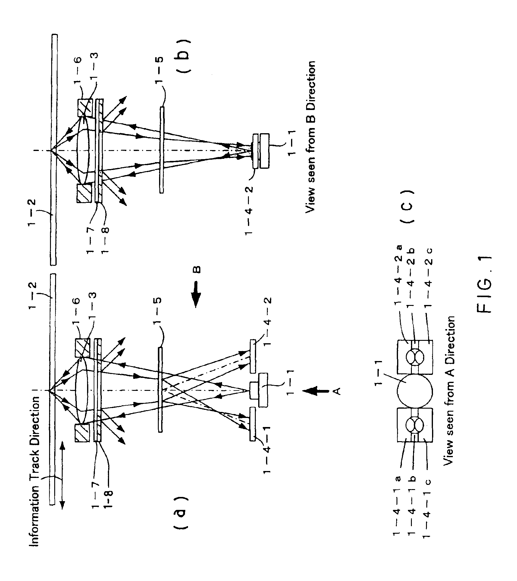
[0047]FIGS. 1(a), 1(b), and 1(c) show structural examples of an optical information processing method according to a first embodiment of the present invention. The description of the same points, such as a detection principle of FE, TE, RF signals as those in the conventional example, shown in FIGS. 18(a) and 18(b) is omitted. In the conventional example, the NA in an incoming path and the NA in a return path are determined by the objective lens holder 18-6 and are equal. In the present embodiment, an aperture is determined by an objective lens holder 1-6, a λ / 4 plate 1-7 that is a component of an aperture element, and a diffraction grating 1-8. The diffracting grating 1-8 is provided with a grating at the portion indicated with hatching in the figure.

[0048]The operation of the aperture element is described as follows. The λ / 4 plate 1-7 has a function of providing a phase difference of λ / 4 to incident light. The diffraction grating 1-8 is a grating having concave and convex portions...

second embodiment

[0056]FIGS. 4(a), 4(b), and 4(c) show structural examples according to a second embodiment of the present invention when the apertures in the incoming and return paths are varied only in the radial direction. The description of the same parts as those in the configuration shown in FIGS. 1(a), 1(b), and 1(c) is omitted. As shown in FIGS. 4(a), 4(b), and 4(c), the aperture formed by an objective lens holder 4-1 in the incoming path and the aperture formed by a diffraction grating 4-2 in the return path are set to be equal in the tangential direction. On the contrary, the aperture NA2 (R) in the return path is set to be smaller than the aperture NA1 (R) in the incoming path in the radial direction shown in FIG. 4(b). In an optical disk system that is affected less by intersymbol interference in the tangential direction, the following advantages are obtained compared to an optical disk system having the configuration shown in FIGS. 1(a), 1(b), and 1(c).[0057](1) Since the aperture NA in...

third embodiment

[0061]FIGS. 7(a), 7(b), and 7(c) show structural examples according to a third embodiment of the present invention when apertures in incoming and return paths are varied only in the tangential direction. The description of the same parts as those in the configurations shown in FIGS. 1(a), 1(b), and 1(c) and 4(a), 4(b), and 4(c) is omitted. As shown in FIG. 7(b), the aperture formed by an objective lens holder 7-1 in the incoming path and the aperture formed by a diffraction grating 7-2 in the return path are set to be equal to each other in the radial direction. On the contrary, in the tangential direction, an aperture NA2(T) in the return path is set to be smaller than an aperture NA1(T) in the incoming path. In an optical disk system that is affected less by crosstalk in the radial direction, the following advantages are obtained compared to the configuration shown in FIGS. 1(a), 1(b), and 1(c).[0062](1) Since the aperture NA in the return path is smaller than that in the incoming...


PUM

PropertyMeasurementUnit
wavelength λ2aaaaaaaaaa
thicknessaaaaaaaaaa
thicknessaaaaaaaaaa

Abstract

An optical disk device has an aperture of an objective lens in an incoming path of a beam from a semiconductor laser to an optical disk formed larger than an aperture in a return path from the optical disk or an aperture is varied in recording and in reproduction. This configuration improves recording / reproducing ability since light is focused on an optical disk with high numerical aperture. In addition, since reflected light from the optical disk is detected with low numerical aperture, margins for tilt and defocus are not reduced. Furthermore, since unnecessary signal components contained in the reflected light can be eliminated, a S / N (signal-to-noise ratio) of an information signal also increases. Thus, a high-performance optical disk device can be obtained. Alternatively, by varying the aperture of an objective lens in recording and in reproduction, an optical disk device in which recording density and recording quality are increased without deteriorating reproduction quality can be obtained.

Description

CROSS REFERENCE TO RELATED APPLICATIONS[0001]This application is a divisional of U.S. patent application Ser. No. 09 / 436,847, filed Nov. 9, 1999 now U.S. Pat. No. 6,618,343.FIELD OF THE INVENTION[0002]The present invention relates to an optical information processor in which information is optically recorded on or reproduced from an optical disk, and to an optical element used in an optical pick-up.BACKGROUND OF THE INVENTION[0003]The operation of an optical head that is one of conventional optical information processors is described with reference to FIGS. 18(a) and 18(b). Light emitted from a semiconductor laser 18-1, an exemplary light source, passes through a hologram 18-5 as a separation element and then is focused on an optical disk 18-2, as an exemplary information recording media, by an objective lens 18-3. After passing through the objective lens, light reflected from the optical disk is diffracted by the hologram and is incident onto first photodetectors 18-4-1 and 18-4-2....

Claims


Application Information

Patent Timeline
Patent Type & Authority Patents(United States)
IPC IPC(8): G11B7/135G11B7/09
CPCG11B7/1353G11B7/139G11B7/09
Inventor SAITOH, YOUICHIASADA, JUNICHITAKAHASHI, YUICHINISHIWAKI, SEIJINAGASHIMA, KENJIMOMOO, KAZUONAGAOKA, JUNJI
Owner PANASONIC CORP
Why Eureka
Try Eureka