Apparatus for measuring and recording data from boreholes

Inactive Publication Date: 2005-01-18
SOLINST CANADA
View PDF5 Cites 51 Cited by
  • Summary
  • Abstract
  • Description
  • Claims
  • Application Information

AI Technical Summary

Benefits of technology

The system as described is aimed at ensuring that a data-gathering from all the modules takes place

Problems solved by technology

However, the instruments and associated apparatus available hitherto have been somewhat inconvenient, especially from the

Method used


Image

  • Apparatus for measuring and recording data from boreholes
  • Apparatus for measuring and recording data from boreholes
  • Apparatus for measuring and recording data from boreholes

Examples


Embodiment Construction

By way of further explanation of the invention, exemplary embodiments of the invention will now be described with reference to the accompanying drawings, in which:

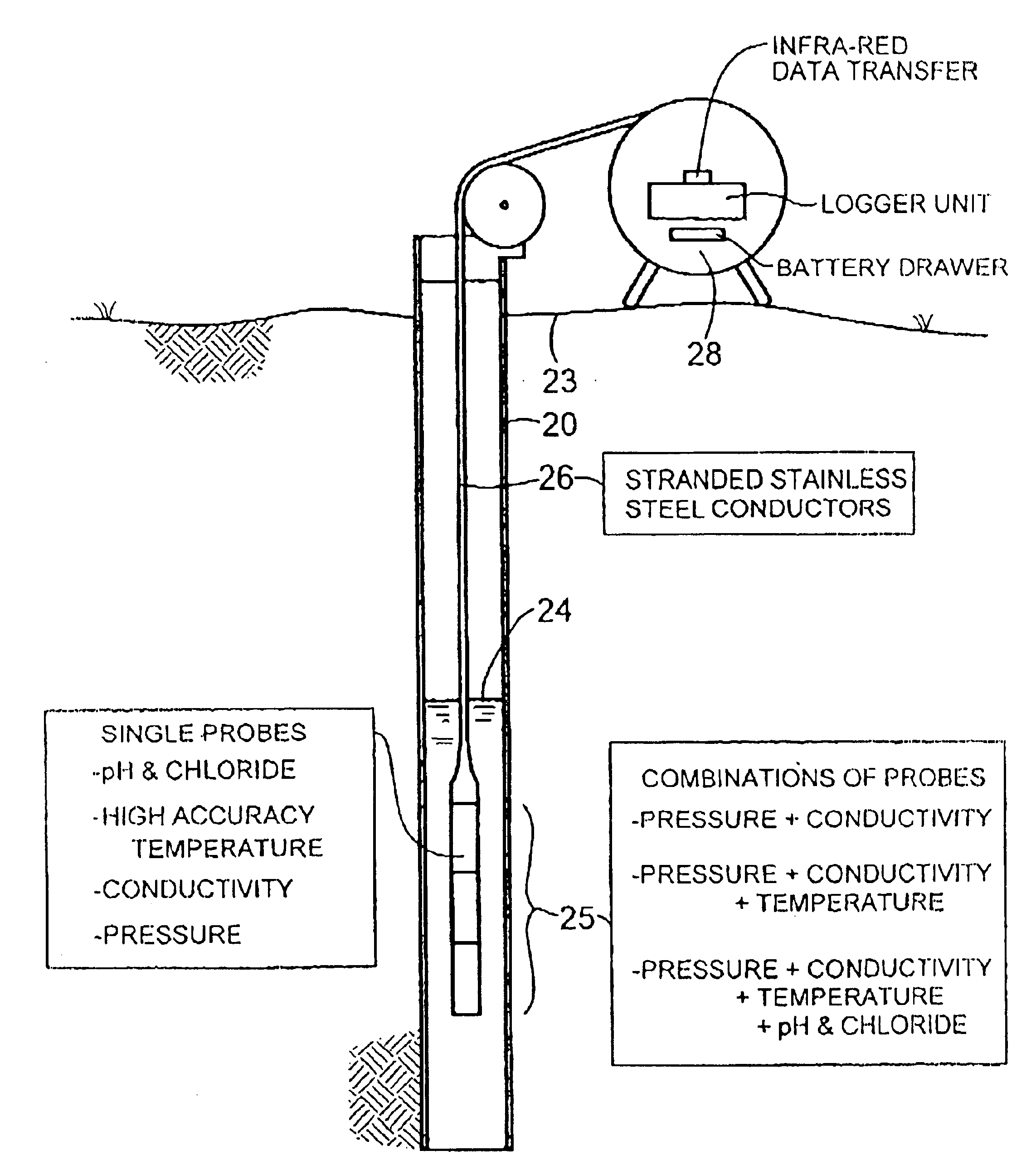
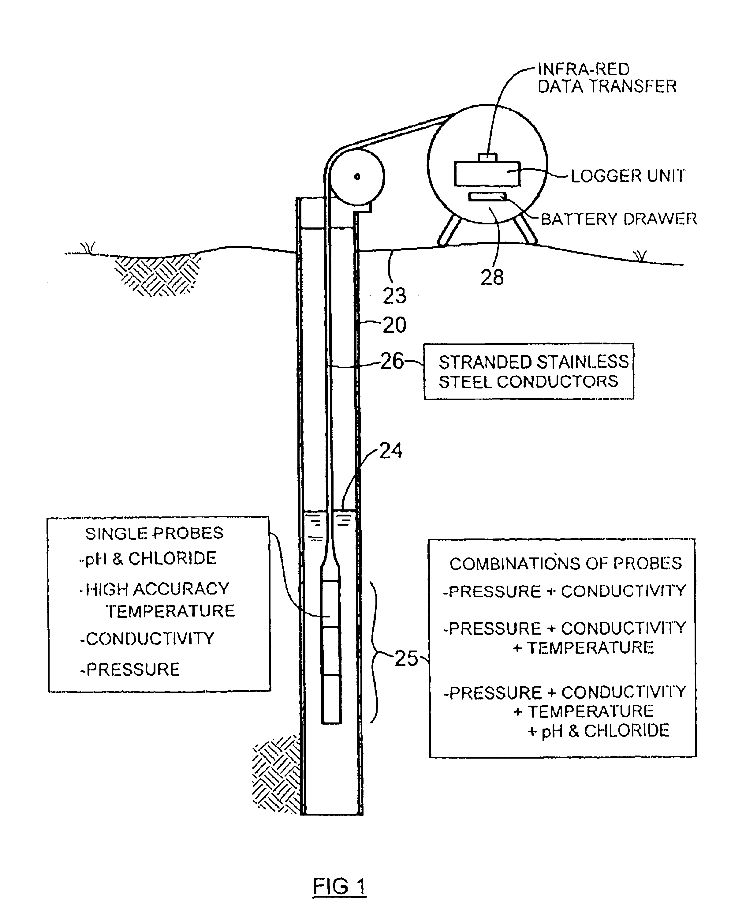
FIG. 1 is diagrammatic side elevation of a borehole or well, in which is located data measuring and collecting apparatus, which includes a string of modules connected to a surface control-unit.

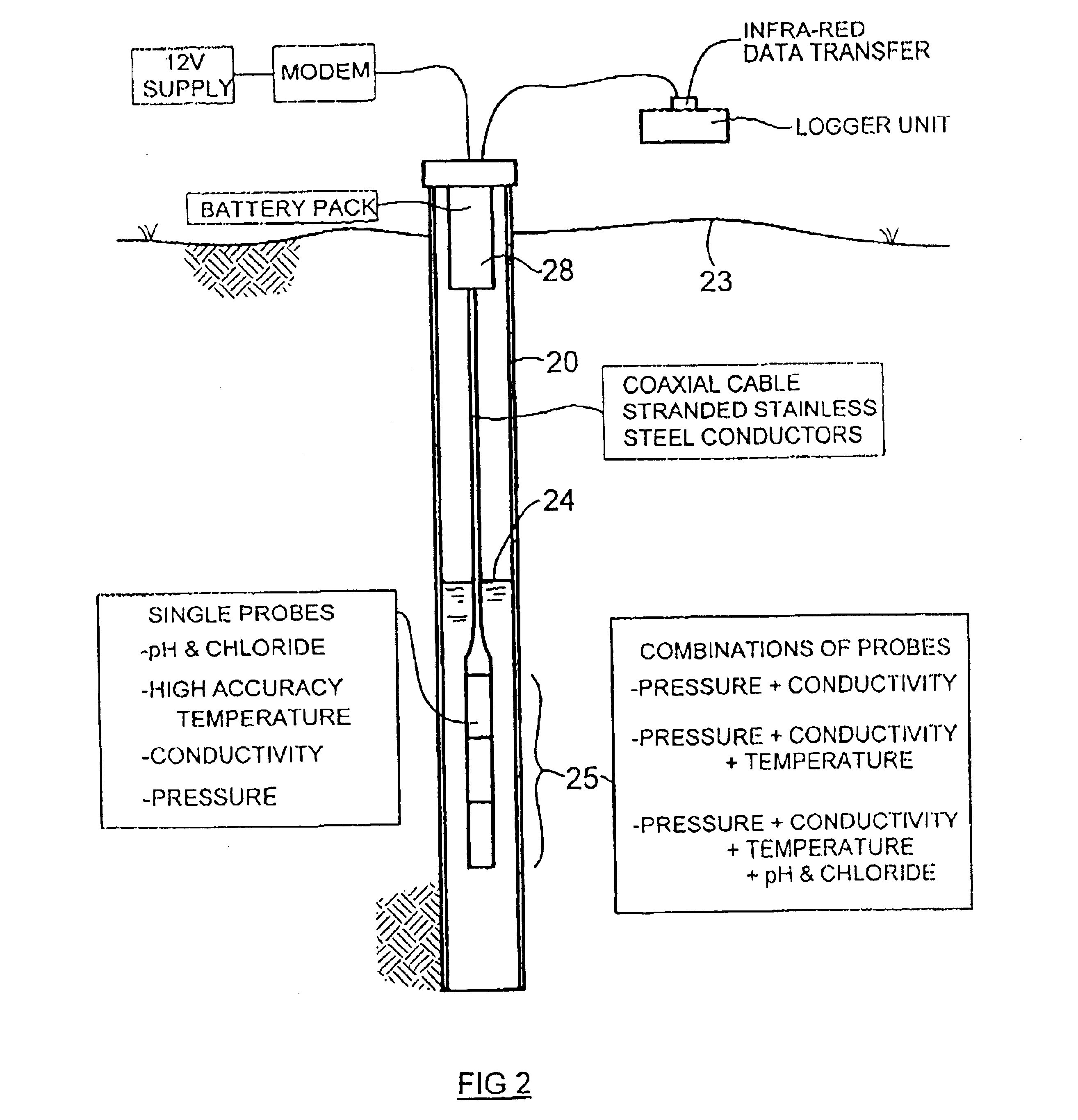
FIG. 2 is a similar view to that of FIG. 1, showing a string of modules connected to a different kind of surface control-unit.

FIG. 3 is a pictorial view of a string of modules.

FIG. 4 is a cross-section of two modules, showing the manner of connection therebetween.

FIG. 5 is a side-view of the bottom and of a cable of the apparatus, and some components associated therewith.

FIG. 6 is a front view corresponding to FIG. 5.

FIG. 7 is a cross-section showing the components of FIGS. 5,6 incorporated into a module.

FIG. 8 is a cross-section like FIG. 7 of a different module.

FIG. 9 is a pictorial view of a portion of a wall of a module, having a...


PUM


Abstract

For collecting data from a water well, down-hole sensors are housed in modules. The modules are arranged to be screwed together in-line to form a vertical string. Mechanically, the modules are secured to each other only by the screw connection. Data is transmitted to the surface on a 2-wire cable, there being no other electrical connection between the modules and the surface. The modules are connected in multi-drop configuration to the 2-wire cable. Data is transmitted using time-division multiplexing.

Description

This invention relates to instruments for taking measurements from wells and boreholes, being measurements of such parameters as water level, water pressure, temperature, and the like. The invention relates particularly to a system for configuring the various sensors, and for co-originating and presenting the data emanating therefrom.BACKGROUND TO THE INVENTIONThe task of gathering data from water wells and boreholes, and from bodies of water generally, has been the subject of much attention. However, the instruments and associated apparatus available hitherto have been somewhat inconvenient, especially from the standpoint of versatility and operational flexibility, and as to the presentation of the data obtained from the boreholes. The invention provides a modular system, which is aimed at easing some of these shortcomings.Generally, the data from sensors, probes, and other instruments in water wells and boreholes is intended to be fed into a computer for final storage and presenta...

Claims


Application Information

Patent Timeline
IPC IPC(8): E21B17/02E21B47/12E21B47/01E21B47/00
CPCE21B17/028E21B47/12E21B47/011E21B47/00E21B47/017
Inventor PATEY, RONALD ERNEST RUSSELLBELSHAW, DOUGLAS JAMES
Owner SOLINST CANADA
Why Eureka
Try Eureka