Eureka AIR delivers breakthrough ideas for toughest innovation challenges, trusted by R&D personnel around the world.

Multi-phase fuel system

Inactive Publication Date: 2005-01-18
EMISSION CONTROLS CORP +1
View PDF15 Cites 20 Cited by
  • Summary
  • Abstract
  • Description
  • Claims
  • Application Information

AI Technical Summary

Benefits of technology

The present invention provides a multi-phase fuel system for an internal combustion engine. More specifically, when the multi-phase fuel system is applied to a vehicle, the higher volatility (lower boiling temperature) components of fuel are supplied to the engine in a gaseous vapor form while the lower volatility (higher boiling temperature) com

Problems solved by technology

The patent also discloses the possibility of continuous operation by directing hot exhaust gases through an optional gas channel that surrounds the body of the injector, but fails to disclose any method of controlling the heat within the device.
As disclosed, this device is only capable of vaporizing liquid fuel during periods of low fuel flow to the engine.
The patent fails to teach or suggest a fuel system capable of converting the lower boiling temperature components of gasoline into vapor, atomizing the higher boiling components, and supplying a combination of the two phases of fuel to the engine for a lean burning mixture.
This system requires extensive modification of the vehicle engine compartment for installation.
This design fails to control the temperature of the apparatus and must maintain reserve vapors for peak demands.
Additionally, due to the location and volume of the fuel vapors, an engine backfire could result in a serious explosion.
However, this system requires the use of complex servomechanisms and sensors.
Due to its complexity, this device is not well suited for retrofitting on existing vehicles with gasoline engines.
The configuration al

Method used


Image

  • Multi-phase fuel system
  • Multi-phase fuel system
  • Multi-phase fuel system

Examples


Example

Although the invention is described in terms of a preferred specific embodiment, it will be readily apparent to those skilled in this art that various modifications, rearrangements and substitutions can be made without departing from the spirit of the invention. The scope of the invention is defined by the claims appended hereto.

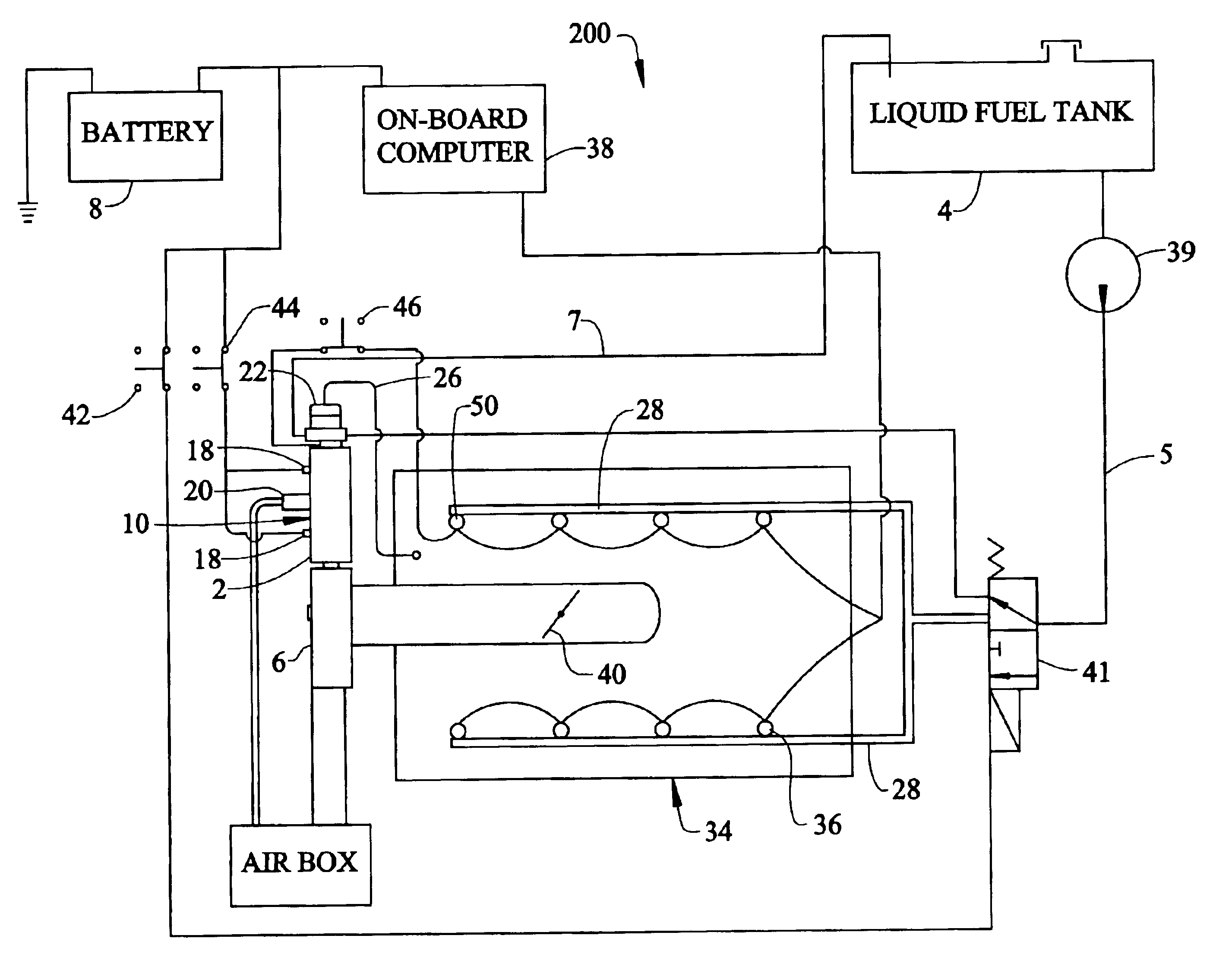
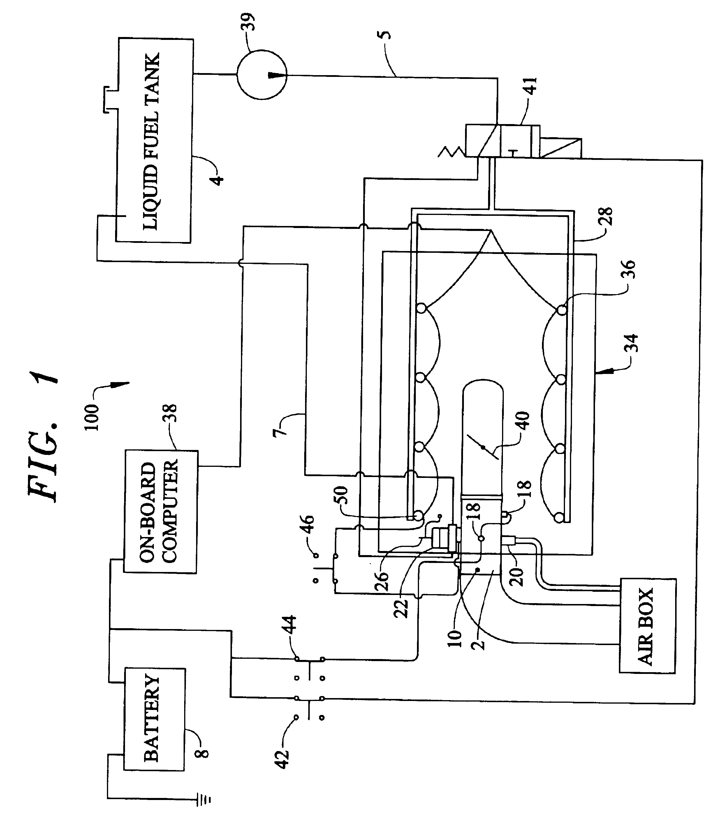
In order to alleviate the problems associated with operating an internal combustion engine entirely from liquid fuel or entirely from vaporized liquid fuel, the present invention utilizes a multi-phase fuel system 100 as set forth in FIG. 1. The multi-phase fuel system separates the components of a single fuel, e.g. gasoline, and delivers the higher volatility (lower boiling temperature) components of the fuel to the engine 34 in a gaseous vaporized form while the lower volatility (higher boiling temperature) components of the fuel are supplied to the engine in an atomized form. The multi-phase fuel system is capable of providing a more optimum lean air / fuel...


PUM


Abstract

The present invention provides a multi-phase fuel system for an internal combustion engine. More specifically, when the multi-phase fuel system is applied to a vehicle, the higher volatility. (lower boiling temperature) components of fuel are supplied to the engine in a vaporized gaseous form while the lower volatility (higher boiling temperature) components of fuel are supplied to the engine in an atomized liquid form. In this manner, the multi-phase fuel system is capable of providing a more optimum lean air/fuel mixture for better fuel economy and emissions control during normal operating conditions while being able to quickly enrich the fuel mixture in response to sudden increases in load demand.

Description

FIELD OF THE INVENTIONThe present invention relates to a multi-phase fuel system for internal combustion engines. More specifically, the system utilizes heat to separate a single fuel into high volatility, e.g. lower boiling temperature, components and low volatility components, e.g. higher boiling temperature. The high volatility components are delivered to the engine as a gaseous vapor containing the atomized lower volatility components. During combustion the highly volatile gaseous vapor promotes complete combustion of the lower volatility atomized components. In this manner the multi-phase fuel system is able to provide improved efficiency and reduced emissions throughout the entire range of engine requirements.BACKGROUND OF THE INVENTIONA fuel system is the component of an internal combustion engine which often has the greatest impact on performance and cost. Accordingly, fuel systems for internal combustion engines have received a significant portion of the total engineering e...

Claims


Application Information

Patent Timeline
IPC IPC(8): F02D19/00F02D19/06F02D19/08F02M1/00F02M1/16F02D19/12F02M21/04F02M31/02F02M31/135F02M31/18F02M35/10
CPCF02D19/0605F02D19/12F02M1/165F02M25/089F02M31/135F02M31/18F02M35/10032F02D19/0649F02D19/0678F02D19/066Y02T10/36F02M35/112Y02T10/121Y02T10/126F02D19/0676Y02T10/12Y02T10/30
Inventor SHETLEY, MICHAEL
Owner EMISSION CONTROLS CORP
Why Eureka
Eureka Blog
Learn More