Inverted lid sealing plate for heat exchanger

Inactive Publication Date: 2005-01-18
DANA CANADA CORP
View PDF13 Cites 45 Cited by
  • Summary
  • Abstract
  • Description
  • Claims
  • Application Information

AI Technical Summary

Benefits of technology

In the present invention, an dish-type end plate configuration is used so that a fluid flow channel can be located between the end plate and the final heat-exchanger plate in th

Problems solved by technology

Such a configuration can result in wasted space, namely, the area surrounded by the portion of the peri

Method used


Image

  • Inverted lid sealing plate for heat exchanger
  • Inverted lid sealing plate for heat exchanger
  • Inverted lid sealing plate for heat exchanger

Examples


Embodiment Construction

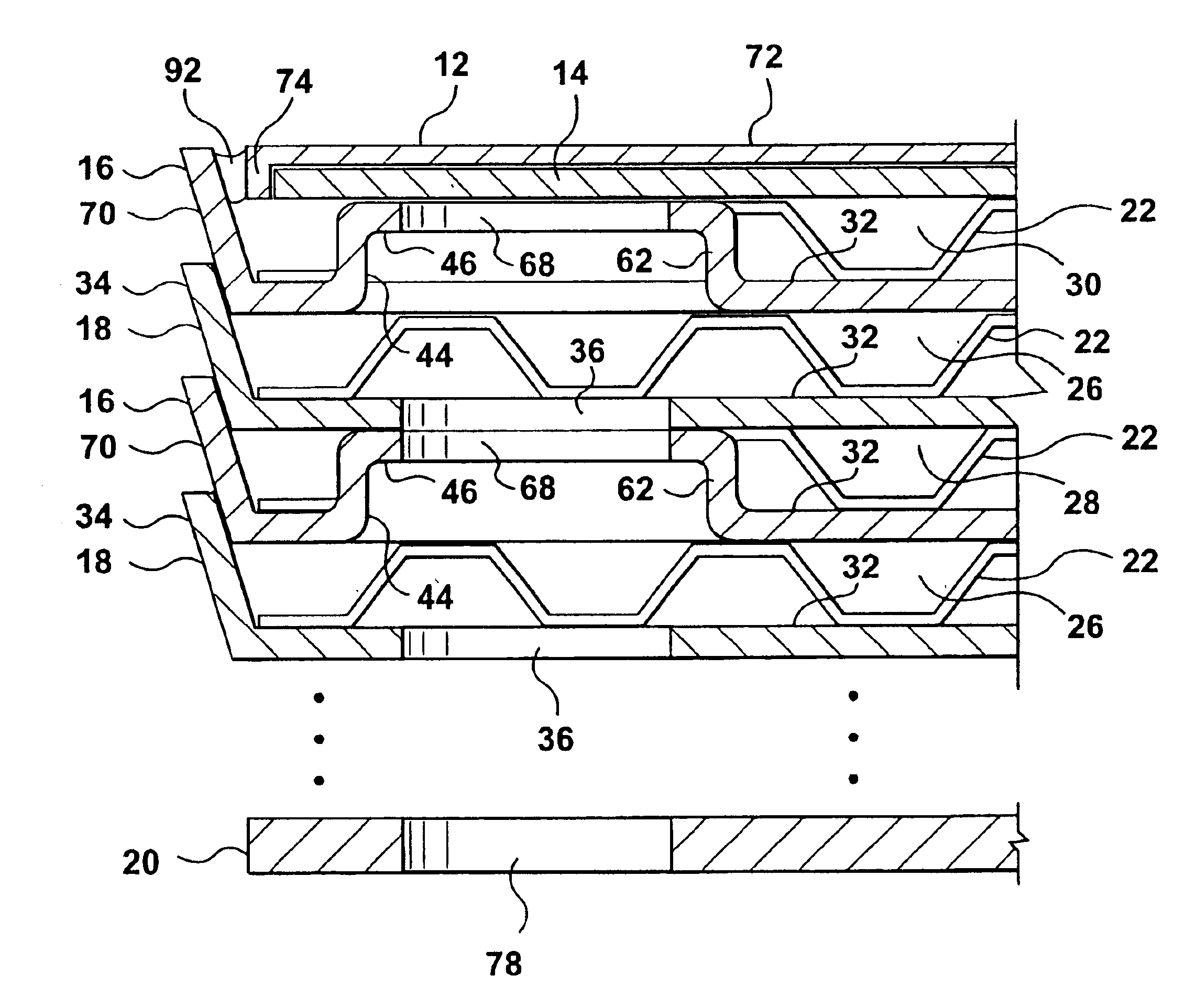
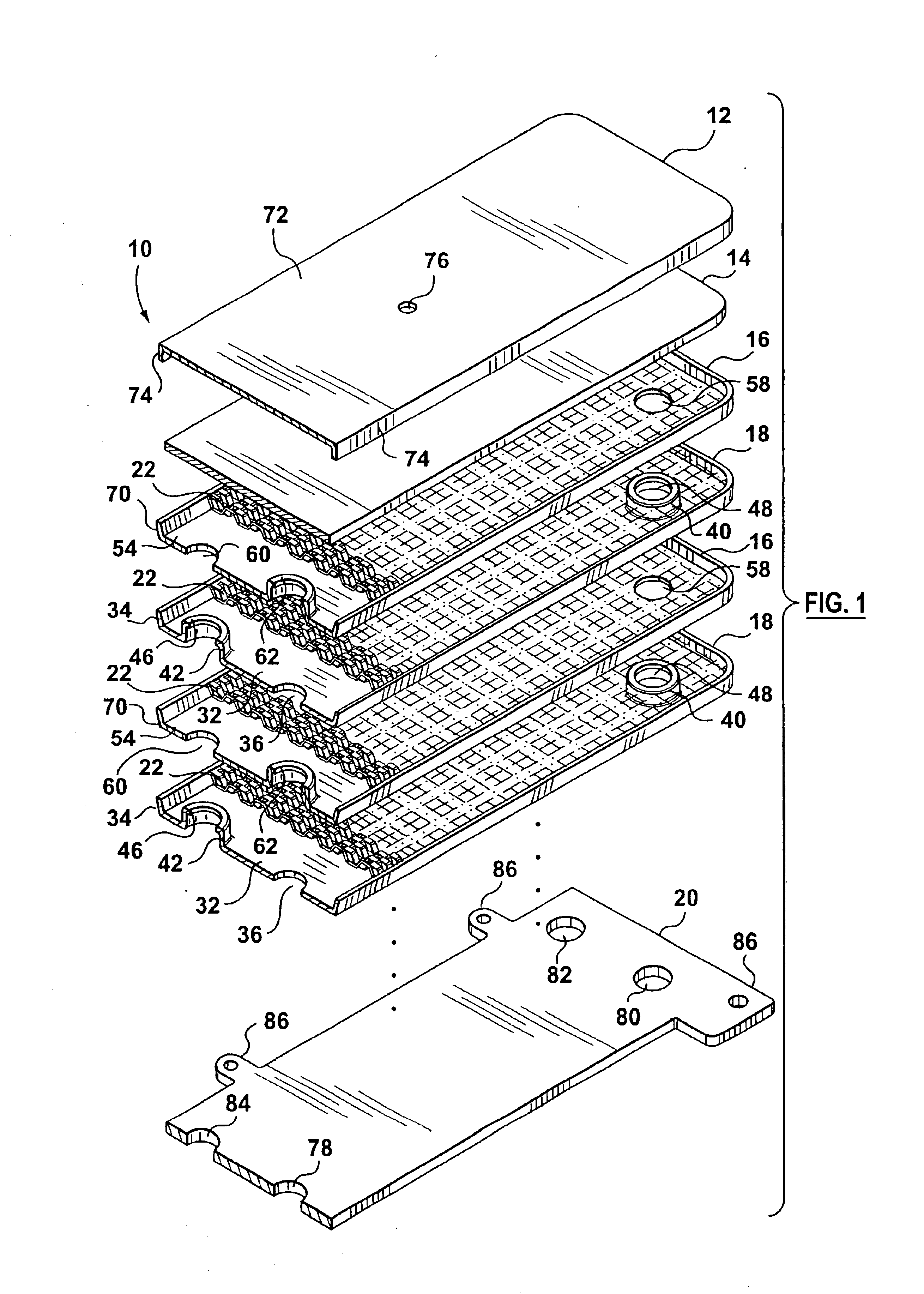
Referring firstly to FIG. 1, an exploded perspective view of a preferred embodiment of a stacked-plate type heat exchanger according to the present invention is generally indicated by reference number 10. The heat exchanger 10 includes an end plate 12, a reinforcing plate 14, a number of alternating nested dish plates 16 and 18, and a connector plate 20. Plates 12 through 20 are shown arranged vertically in FIG. 1, but this is only for the purposes of illustration. The heat exchanger 10 can have any orientation desired.

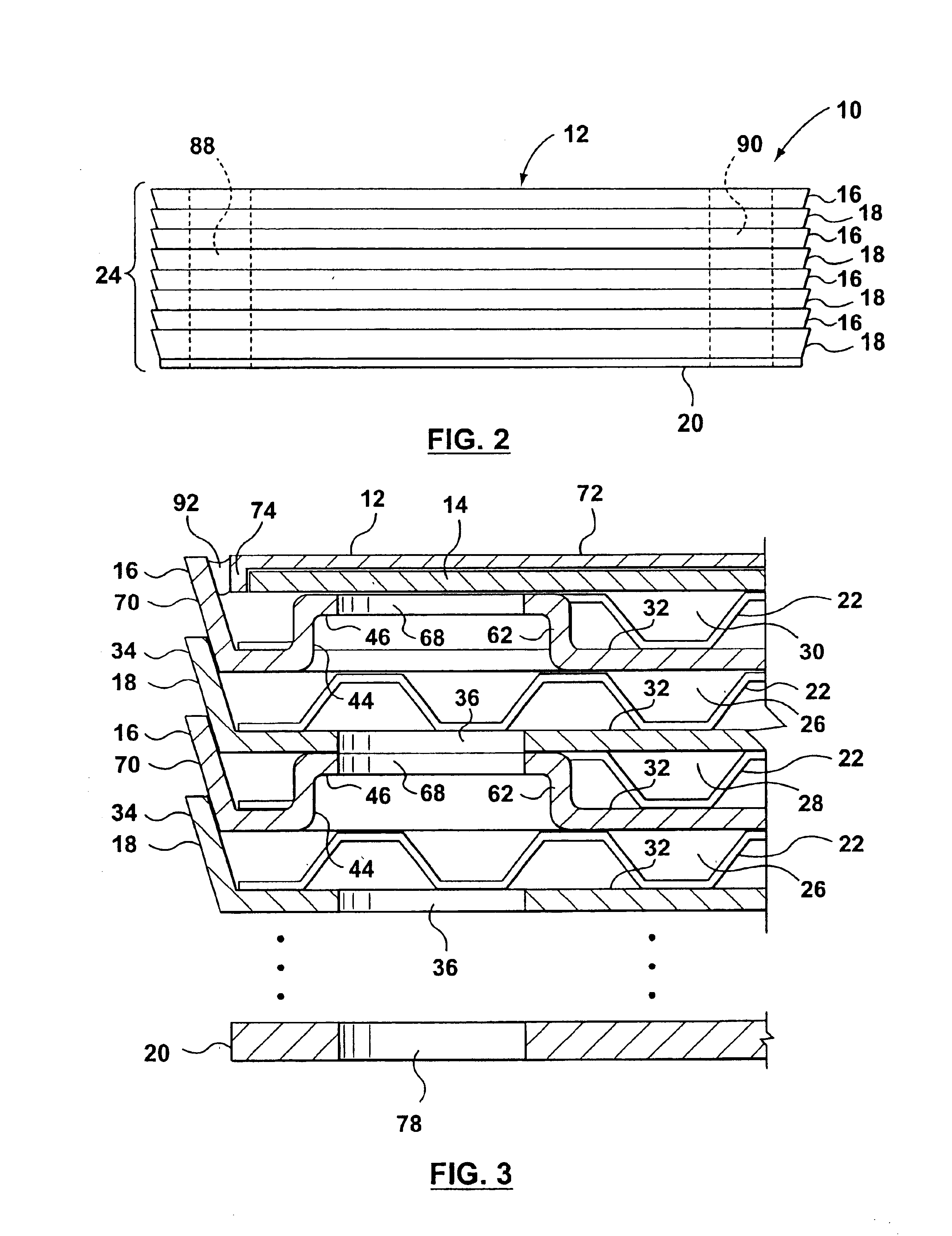
In one preferred embodiment, the plates 12-20 are each formed from braze clad aluminum or aluminum alloy, however, other materials such as stainless steel or copper alloy, for example, could also be used. With reference to FIG. 2, the dish-style heat exchanger plates 16 and 18 are alternatively stacked one next to the other to form a core heat exchanger stack 24. With reference to FIG. 3, first fluid flow channels 26 and second fluid flow channels 28 for respective fi...


PUM


Abstract

A stacked plate-type heat exchanger including a plurality of dish-shaped heat exchanger plates arranged one next to the other to form a nested heat exchanger plate stack. A plurality of first and second fluid flow channels are formed between the heat exchanger plates for first and second fluids respectively, and first fluid and second fluid chambers are formed in the stack in communication with the first and second fluid channels respectively. An end plate for the heat exchanger has an end plate central planar portion and a peripheral flange projecting from the end plate central planar portion, the peripheral flange of the end plate projecting in an opposite direction and sealably nested within the peripheral flange of a final heat exchanger plate in the plate stack. A planar reinforcing plate is secured to an inner surface of the end plate central planar portion between the end plate central planar portion and the final heat exchanger plate, a further fluid channel for one of the first and second fluids being located between the planar reinforcing plate and the final heat exchanger plate.

Description

This application claims priority to Canadian Application No. 2,383,649 filed Apr. 24, 2002.BACKGROUND OF THE INVENTIONThis invention relates to heat exchangers of the type formed from dish-shaped heat exchanger plates.One form of plate-type heat exchangers includes a plurality of plates secured together in a stacked assembly with gaskets or bosses located between adjacent plates and traversing a course adjacent to the plate peripheries. Flow of two fluids involved in heat exchange is through alternate layers defined by the stacked plates. The stacked plates are typically joined together as a unitary structure by brazing the various components together. Examples of such plate-type heat exchangers are disclosed, for example, in U.S. Pat. No. 5,931,219 issued to Kull et al. and U.S. Pat. No. 4,872,578 issued to Fuerschbach et al.A characteristic of previously proposed nested-dish heat exchangers is that in order to provide strength to the heat exchanger stack, the heat exchanger plates...

Claims


Application Information

Patent Timeline
IPC IPC(8): F28F27/00F28F3/00F28F27/02F28F3/02F28D9/00F28F3/08F28D9/02F28F9/00
CPCF28D9/005F28F3/027F28F9/026F28F2280/04Y10S165/916F28F2225/04
Inventor EVANS, BRUCE L.ST. PIERRE, MIKEENGLISH, JOE L.
Owner DANA CANADA CORP
Why Eureka
Try Eureka