
Display panel

a display panel and display technology, applied in the field of display panels, can solve the problems of low aperture ratio of pixels in the conventional oled display panel, and achieve the effect of increasing the aperture ratio of pixels

Active Publication Date: 2021-10-28
WUHAN CHINA STAR OPTOELECTRONICS SEMICON DISPLAY TECH CO LTD
View PDF2 Cites 0 Cited by
  • Summary
  • Abstract
  • Description
  • Claims
  • Application Information

AI Technical Summary

Benefits of technology

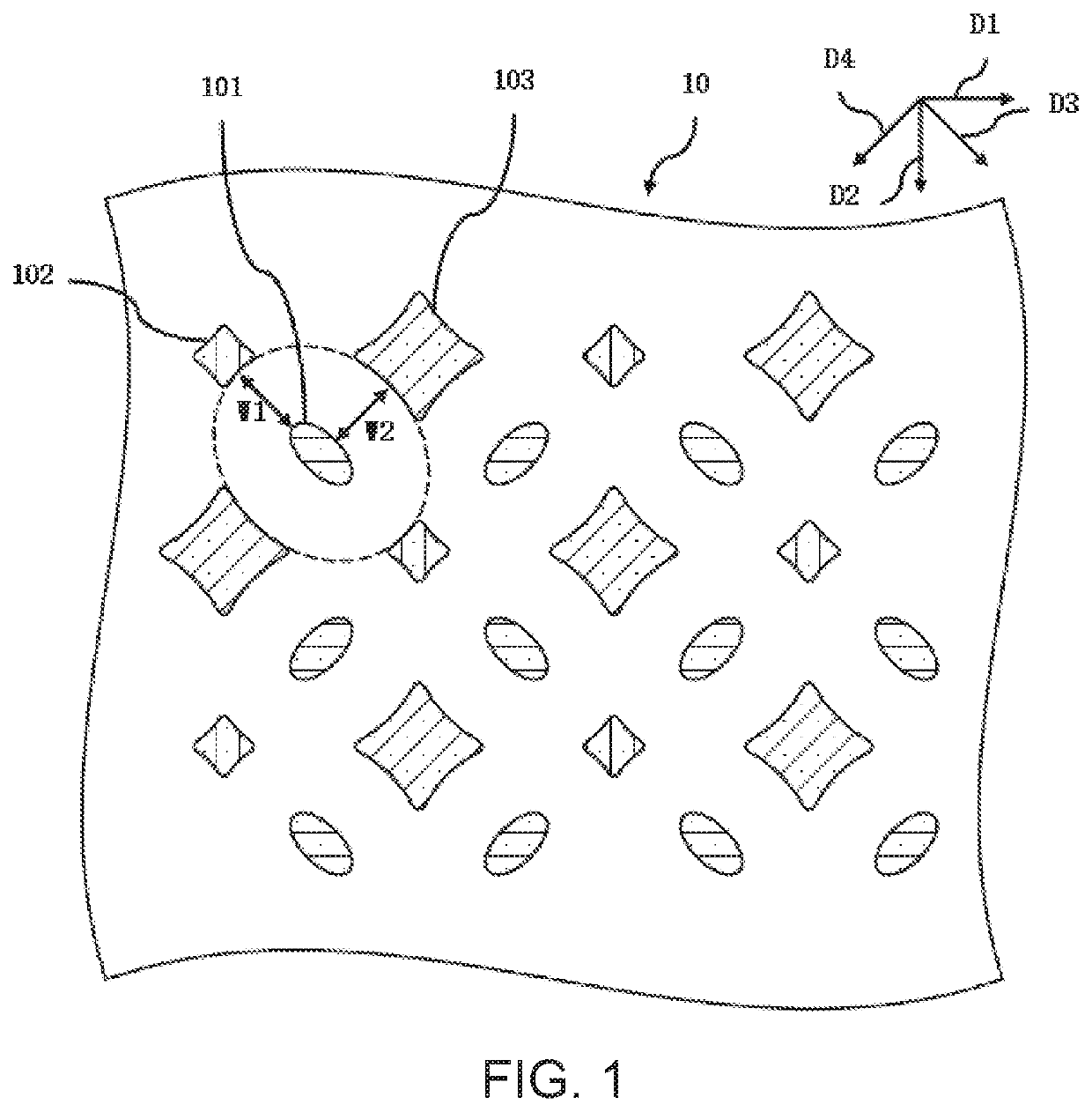
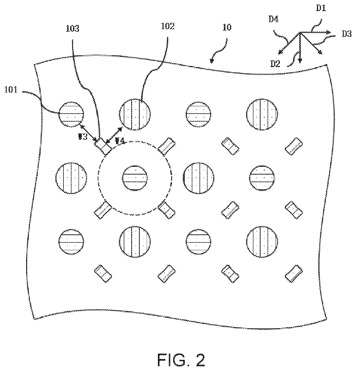
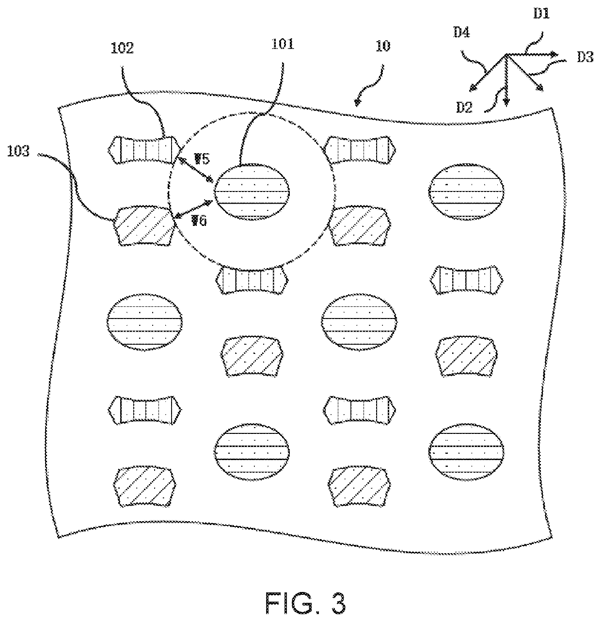
The present invention provides a display panel that can increase the aperture ratio of pixels effectively. The shape of the first pixels is designed as a circle or ellipse, while the shape of the edge of the second and third pixels is concave. This results in a reduced unused space between pixels, which ultimately increases the aperture ratio of the pixels.

Problems solved by technology

Due to limitations of shapes of the pixels and a gap between the pixels, unused spaces between the pixels in the conventional OLED display panels are large, and thus aperture ratios of the pixels in the conventional OLED display panels are low.

Method used


Image

  • Display panel
  • Display panel
  • Display panel

Examples


Embodiment Construction

[0047]The term “embodiment” as used in this specification means an embodiment, an example, or an illustration. In addition, the article “a” as used in the specification and the appended claims may be construed as “one or more.” The singular form can be clearly defined unless otherwise specified or from the context.

[0048]Any two of a first embodiment, a second embodiment, a third embodiment, and a fourth embodiment of a display panel 10 of the present disclosure are similar or same.

[0049]In the first embodiment, the second embodiment, the third embodiment, and the fourth embodiment of the present disclosure, the display panel 10 can be, for example, an organic light emitting diode (OLED) panel or the like.

[0050]The display panel includes at least two pixel repeating units, and the at least two pixel repeating units are arranged in an array (one-dimensional array or two-dimensional array). The pixel repeating unit includes one first pixel 101, one second pixel 102, one third pixel 103...


PUM


Abstract

A display panel is provided. At least two of each of first pixels, each of second pixels, and each of third pixels of the display panel are alternately arranged. A shape of each of first pixels includes an ellipse or a circle. A shape of an edge of each of the second pixels or each of the third pixels corresponds to a concave arc. A sum of a radius of curvature of an edge of each of the first pixels and a width of a predetermined gap is equal to a radius of curvature of the concave arc corresponding to the edge of one of each of the second pixels and each of the third pixels. An aperture ratio of a pixel is effectively increased.

Description

FIELD OF INVENTION[0001]The present disclosure relates to the field of display technologies, and more particularly to a display panel.BACKGROUND OF INVENTION[0002]Luminescent material layers of pixels in conventional organic light emitting diode (OLED) display panels are generally formed by evaporation processes. In processes of forming the luminescent material layers of the pixels, a certain gap needs to be reserved between the luminescent material layers of the adjacent two pixels to prevent luminescent materials of different pixels from interfering with each other.[0003]Due to limitations of shapes of the pixels and a gap between the pixels, unused spaces between the pixels in the conventional OLED display panels are large, and thus aperture ratios of the pixels in the conventional OLED display panels are low.[0004]Therefore, it is necessary to propose a new technical solution to solve the above technical issues.SUMMARY OF INVENTION[0005]An object of the present disclosure is to ...

Claims


Application Information

Patent Timeline
IPC IPC(8): H01L27/32
CPCH01L27/3216H01L27/3218H10K59/352H10K59/353H10K71/166
Inventor ZHAO, YONGSUN, LIANGWANG, SHOUCHENGCHANG, YAOJEN
Owner WUHAN CHINA STAR OPTOELECTRONICS SEMICON DISPLAY TECH CO LTD
Learn More