Piezoelectric body module and manufacturing method therefor

a technology of piezoelectric body and manufacturing method, which is applied in the direction of transducer casing/cabinet/support, microphone structural association, electrical transducer, etc., can solve the problems of enlargement of the size of the resin substrate, insufficient miniaturization, and inability to achieve miniaturization of the whole microphone module, so as to reduce the unused space

Active Publication Date: 2012-11-13
TDK CORPARATION
View PDF6 Cites 0 Cited by
  • Summary
  • Abstract
  • Description
  • Claims
  • Application Information

AI Technical Summary

Benefits of technology

[0010]According to the present invention, miniaturization of the piezoelectric body module can be achieved, by adopting the rhombus-shaped piezoelectric element as the first electronic part and the polygonal-shaped amplifying element as the second electronic part, and by arranging, on the rectangular substrate, the first electronic part, the second electronic part, and an electrode land so as to reduce the unused space while ensuring a space to conduct a wire bonding.
[0011]The present invention is intended for miniaturization of the piezoelectric body module, and is useful in miniaturization and weight reduction of a mobile device and the like, such as a mobile phone.

Problems solved by technology

Furthermore, electrode lands are arranged around these chips, leading to an enlargement of the size of the resin substrate.
As described above, the microphone module disclosed in patent document 1 includes wasted area that leads to an enlarged size, thus the miniaturization is not conducted sufficiently.
Presently, a more miniaturized microphone chip having a rhombus shape is available; however, if the conventional arrangement were to be applied, a miniaturization of the whole microphone module cannot be achieved even when the square microphone chip is substituted with a more miniaturized rhombus-shaped microphone chip, merely increasing the size of the unused space on the resin substrate.

Method used


Image

  • Piezoelectric body module and manufacturing method therefor
  • Piezoelectric body module and manufacturing method therefor
  • Piezoelectric body module and manufacturing method therefor

Examples


Embodiment Construction

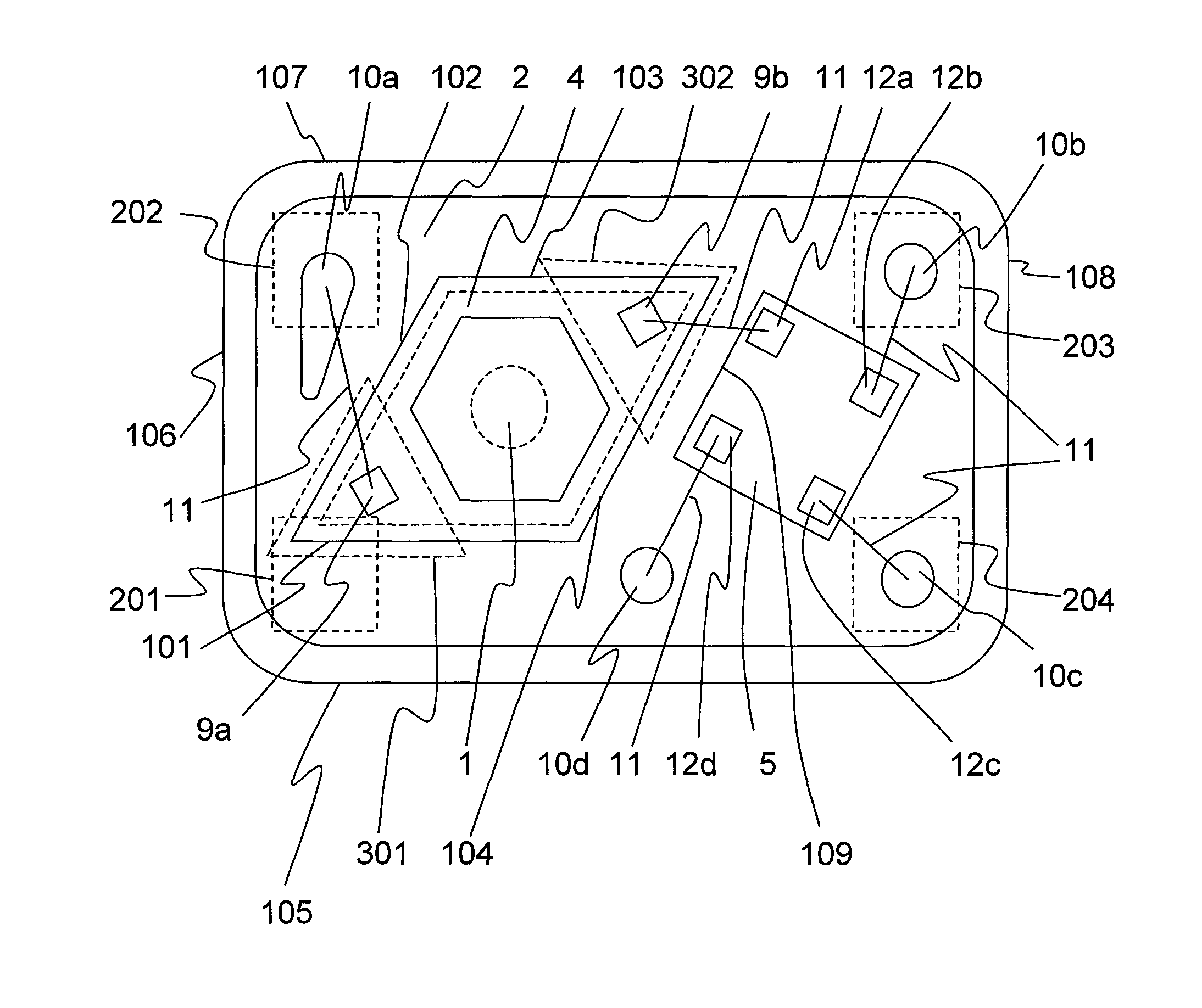
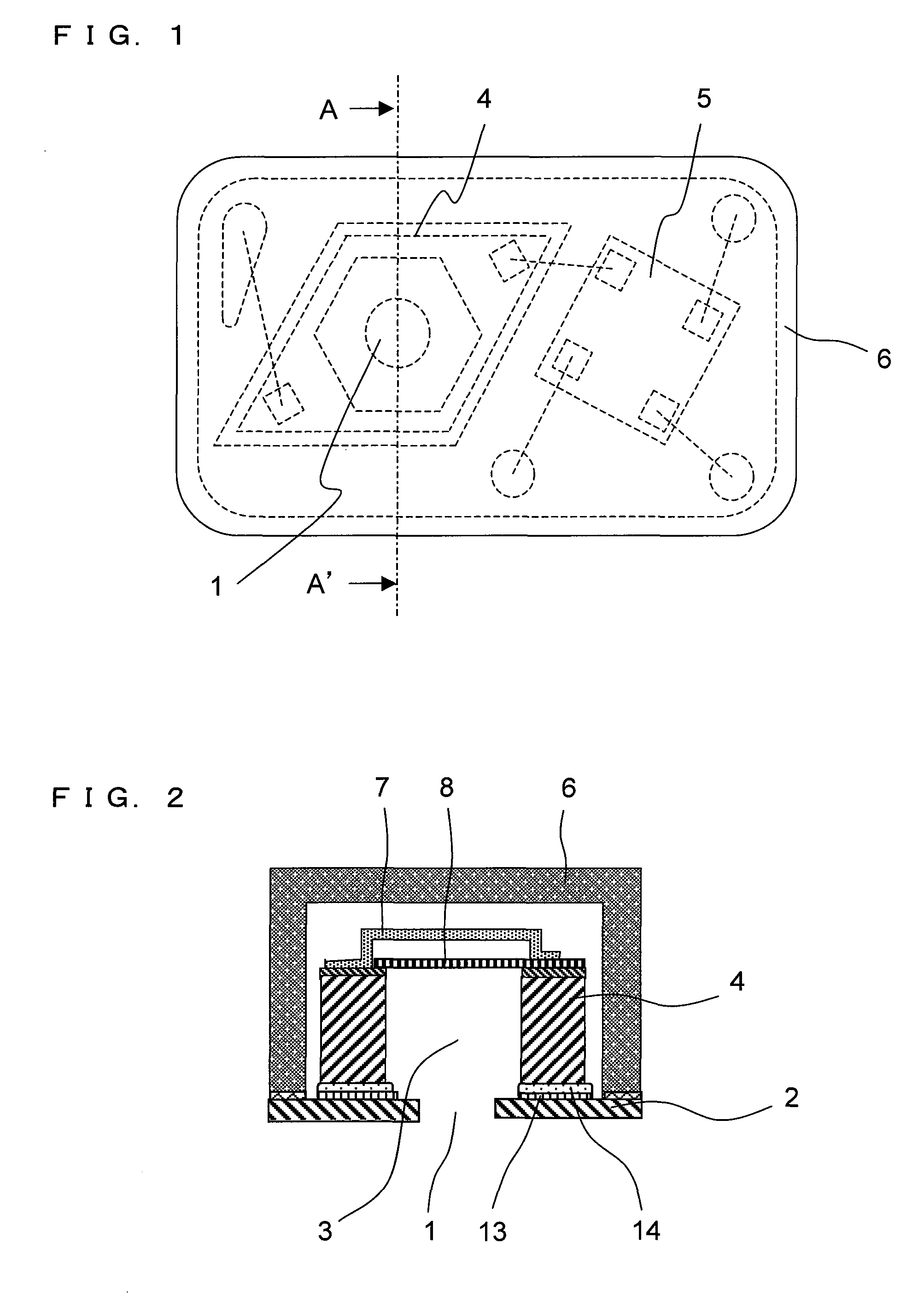
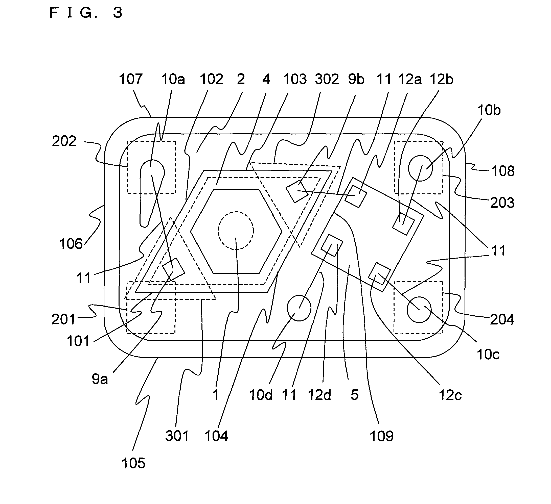
[0028]An embodiment according to the present invention will be described in the following with reference to drawings. As shown in FIG. 1 and FIG. 2, a silicon microphone module (piezoelectric body module) according to the current embodiment includes: a sound hole 1 for introducing a sound; a substrate 2 having a rectangular shape; a first electronic part 4 having a rhombus shape; a second electronic part having a polygonal shape; and a cap 6 that covers the first electronic part 4 and the second electronic part 5. In the current embodiment, the substrate 2 is a resin substrate 2 obtained by impregnating a material with a resin. Furthermore, the first electronic part 4 is a silicon microphone chip (a piezoelectric element) 4 including a hexagonal opening portion 3 in a position above the sound hole 1; and the second electronic part 5 is a CMOS amplifier chip (an amplifying element) 5. The silicon microphone chip 4 and the CMOS amplifier chip 5 are fixed on the resin substrate 2 via a...


PUM

PropertyMeasurementUnit
lengthaaaaaaaaaa
distanceaaaaaaaaaa
acute angleaaaaaaaaaa

Abstract

In order to miniaturize a piezoelectric body module, in which a rhombus-shaped electronic part 4 and a polygonal-shaped electronic part 5 are arranged on a rectangular substrate 2: the rhombus-shaped electronic part 4 is arranged on the substrate 2 such that a side 105 of the substrate 2 and a side 101 of the rhombus-shaped electronic part 4 are parallel to each other; and the polygonal-shaped electronic part 5 is arranged on the substrate 2 such that a side 104 of the rhombus-shaped electronic part 4 and a side 109 of the polygonal-shaped electronic part 5 are parallel to each other.

Description

BACKGROUND OF THE INVENTION[0001]1. Field of the Invention[0002]The present invention relates to a piezoelectric body module that is used in a mobile phone, a hearing aid, and the likes. In particular, the present invention relates to a structure of a piezoelectric body module adapting to a miniaturization of a mobile phone, a hearing aid, and the like; and a manufacturing method of the piezoelectric body module.[0003]2. Description of the Background Art[0004]In recent years, MEMS (Micro-Electro-Mechanical Systems) technology that uses semiconductor microfabrication technologies for forming an electromechanical part is gathering attention; and development of MEMS technology is active in various fields, such as the machinery field, the electronics field, the communication field, the medical field, and the like. One example is a development of a technology that allows a miniaturization of a microphone module by mounting a microphone chip and an amplifier chip on the same substrate.[00...

Claims


Application Information

Patent Timeline
Patent Type & Authority Patents(United States)
IPC IPC(8): H04R25/00H01L29/84H04R1/02H04R19/04H04R31/00
CPCH04R1/04H04R17/02Y10T29/42H01L2224/45144H01L2224/48137H01L2924/3025H01L2924/1461H01L2224/85207H01L2224/45124H01L2224/45015H01L2224/05644H01L2224/05624H01L24/45H01L2224/48624H01L2924/01014H01L2924/00H01L2924/00014H01L2924/20751H01L2924/20752H01L2924/20753H01L2224/48644H01L2224/48724H01L2224/48744H01L2224/05554H01L2224/49171H01L2924/01029
Inventor MIZUTANI, ATSUHITOKOJIMA, HIDEKIMAKIHATA, KATUHIRO
Owner TDK CORPARATION
Why Eureka
Try Eureka