Stripping device for the return run area of conveyor belts

a technology of conveyor belts and stripping devices, which is applied in the direction of work treatment devices, brushing, vehicle maintenance, etc., can solve the problems of longer return times, achieve the effect of restoring force, shortening the interruption of stripping operation, and facilitating the reaction of stripping lamellas

Inactive Publication Date: 2005-01-18
KILL FRECH CORNELIA
View PDF10 Cites 40 Cited by
  • Summary
  • Abstract
  • Description
  • Claims
  • Application Information

AI Technical Summary

Benefits of technology

When an obstruction fast adhering to the belt, e.g. a so-called belt damage, impacts on the stripping lamella, the stripping lamella may easily leave its stripping position on the belt. The stripping lamella at its stripping edge is engaged by the obstruction, and taken along. This can lead to a swivelling motion about the swivel axis of the top swivel mount, where the spring force and therefore the restoring force of the biased spring means increases. Overlapping with this swivelling motion of the stripping lamella is a counter-sense swivelling motion of the lamella holder about the bottom swivel mount caused by the reaction forces of the belt transmitted by the stripping lamella. This results in a further increase of the spring action of the spring means acting on the bottom swivel mount so that the restoring force is increased here as well. During this swivelling motion, at the time when the distance from the top swivel axis to the belt is increased to a length of the distance between the top swivel axis and the stripping edge or earlier, the stripping lamella starts getting out of engagement with the obstruction, and the obstruction may pass under the stripping lamella.
The sequence of the two overlapping swivel motions is essentially dependent on the mass forces, in particular in the area of the stripping lamella and the top swivel mount, including the spring means acting there and on the torques resulting therefrom. The smal

Problems solved by technology

Because even small irregularities on the belt would result in short lifting off of the stripping lamella, in particular with higher velocities, sometimes even result

Method used


Image

  • Stripping device for the return run area of conveyor belts
  • Stripping device for the return run area of conveyor belts
  • Stripping device for the return run area of conveyor belts

Examples


Embodiment Construction

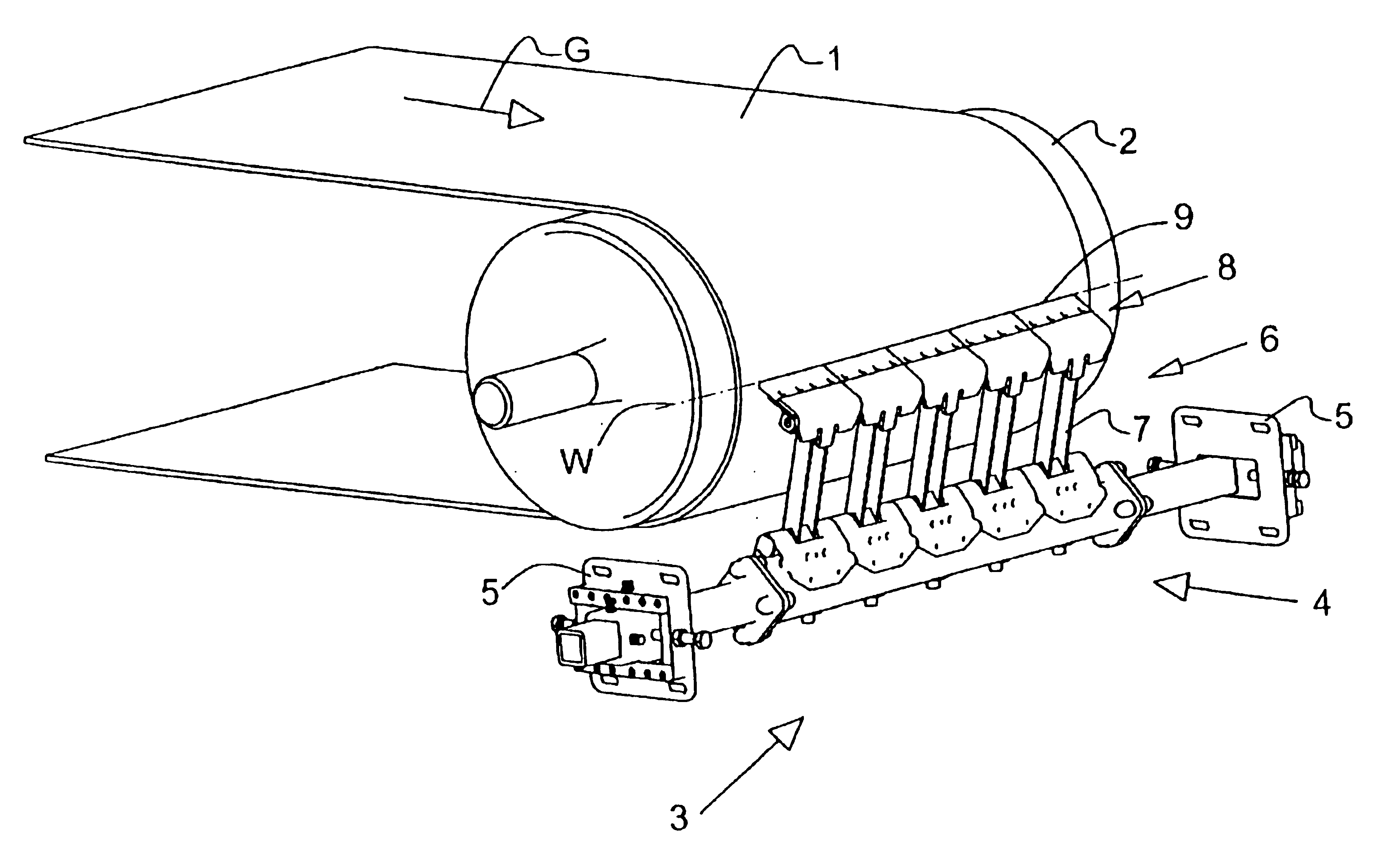
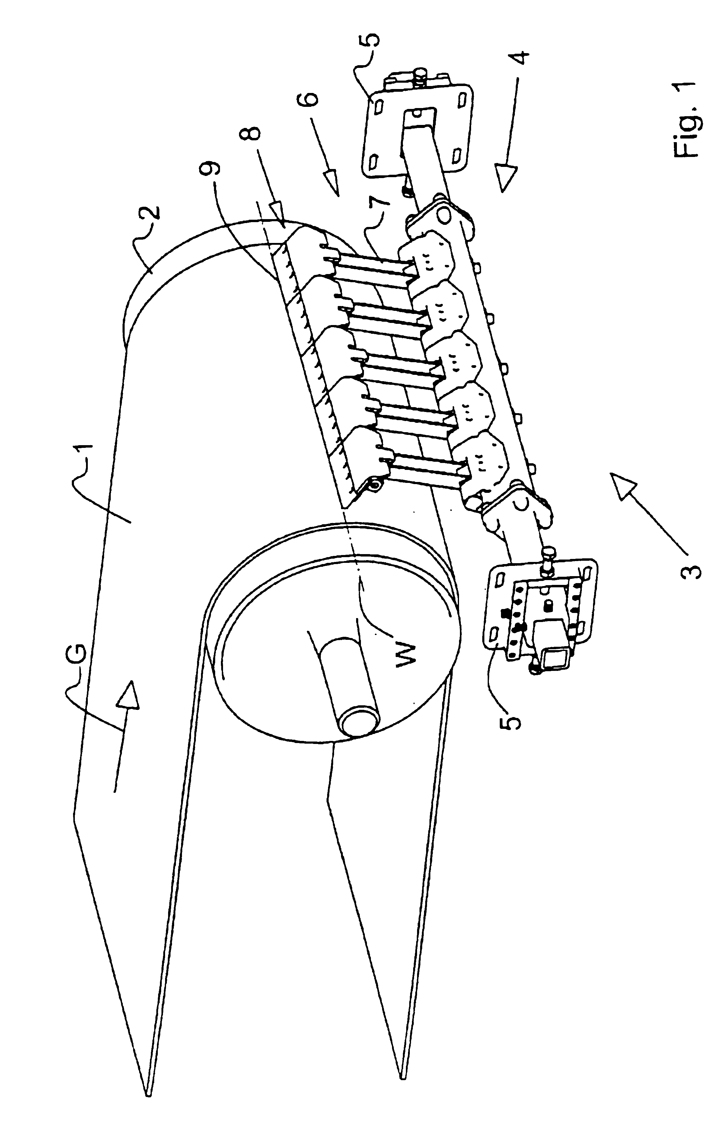
With reference to FIG. 1, about a pulley 2—drive and / or head pulley—a belt 1 is placed running round the pulley 2 in a belt running direction indicated by an arrow G, in this case having an angle of contact of about 90°. The pulley 2 is supported in the usual way to be rotary within a frame (not shown) of a conveyor belt assembly.

At the head of the belt 1, as a pre-stripper, a means 3 is arranged for stripping dirt off the belt 1. On a system carrier 4 supported by means of lateral supports 5 at both its ends in a frame (not shown) of the conveyor belt assembly, there are five stripping elements 6 in a row immediately adjacent to each other. Each stripping element 6 is mounted on the system carrier 4 by way of a lamella holder 7 and carries a stripping lamella 8 on top (indications like “top” or “horizontal” or the like here and in the following principally refer to the position of use of the stripping element 6) the stripping lamella 8 in the stripping operation closely contacting ...


PUM

PropertyMeasurementUnit
Angleaaaaaaaaaa
Angleaaaaaaaaaa
Angleaaaaaaaaaa

Abstract

Apparatus for stripping a belt in conveyor belt assemblies includes a stripping element on a system carrier, the stripping element having a stripping lamella on a lamella holder, the stripping lamella contacting the belt in a peeling position, wherein the stripping element has a swivel mount coupled to the lamella holder and a swivel axis parallel to a plane of the belt, a spring for pressing the stripping lamella against the belt such that the lamella holder in the peeling position is swiveled about the horizontal axis, and when obstructions adhering to the belt impact the stripping lamella, the lamella holder deflects and returns a working position, wherein the stripping lamella is swivel mounted at the lamella holder by a swivel mount having an axis parallel to a plane of the belt and is held and spring biased by a top spring is counter to the bottom swivel mount spring.

Description

BACKGROUND OF THE INVENTIONThe present invention relates to a device for stripping dirt off belts in conveyor belt systems in the area of a drive and / or head pulley of the belt.comprising a system carrier to be attached to a belt carrier frame,at which at least one stripping element is arranged,the stripping element having a stripping lamella mounted on a lamella holder,the stripping lamella contacting the belt in a peeling position,and wherein the stripping element has a bottom swivel mount coupled to the lamella holder and having a horizontal swivel axis—indications such as “horizontal” or the like here and in the following principally refer to the position of use of the stripping elementas well as a spring means acting to press the stripping lamella on the lamella holder against the belt in such a form and arrangementthat the lamella holder in the stripping position of the stripping lamella is swivelled about the horizontal swivel axis in a spring loaded fashion,and, when obstruc...

Claims


Application Information

Patent Timeline
IPC IPC(8): B65G45/00B65G45/16
CPCB65G45/16
Inventor SCHWARZE, HANS-OTTO
Owner KILL FRECH CORNELIA
Why Eureka
Try Eureka