Machine tool

a machine tool and tool body technology, applied in the field of machine tools, can solve the problems of low work efficiency, spindle vibration, and difficult to achieve the stability of the second saddle,

Inactive Publication Date: 2005-01-18
HORKOS
View PDF10 Cites 14 Cited by
  • Summary
  • Abstract
  • Description
  • Claims
  • Application Information

AI Technical Summary

Benefits of technology

According to this, the first saddle guides the second saddle through at least three guide route means. Besides, two opposite guide route means in longitudinal direction among these have longitudinal floating regulated by the second saddle part therebetween strictly. Therefore, the second saddle can secure position stability at an optional position in the lateral moving range thereof.
According to this, when the upper and lower parts of the second saddle are reinforced as a spindle head supporting member, the supporting member effectively contributes as a support structure of two guide route means at the upper and lower positions of the first saddle and transmits floating control force of two guide route means to the second saddle.
According to this, the guide route means are easily formed by well-known means, and the route members and the interfitting members can relatively slide on the first saddle to the second saddle in the state where floating is controlled.
In a machine tool according to the present invention, a spindle head can stably move in the state where inclination displacement due to component floating of the guide route means is hard to occur because of its own weight.

Problems solved by technology

In this machine tool, when the first saddle and the second saddle are moved in vertical and lateral direction or when the spindle head is moved in longitudinal direction, the second saddle is hard to attempt the position stability.
Unless the second saddle has sufficient position stability, there occurs the problem that a spindle vibrates and working can not be carried out high-accurately.

Method used


Image

  • Machine tool
  • Machine tool
  • Machine tool

Examples


Embodiment Construction

The invention will be described with reference to the drawings.

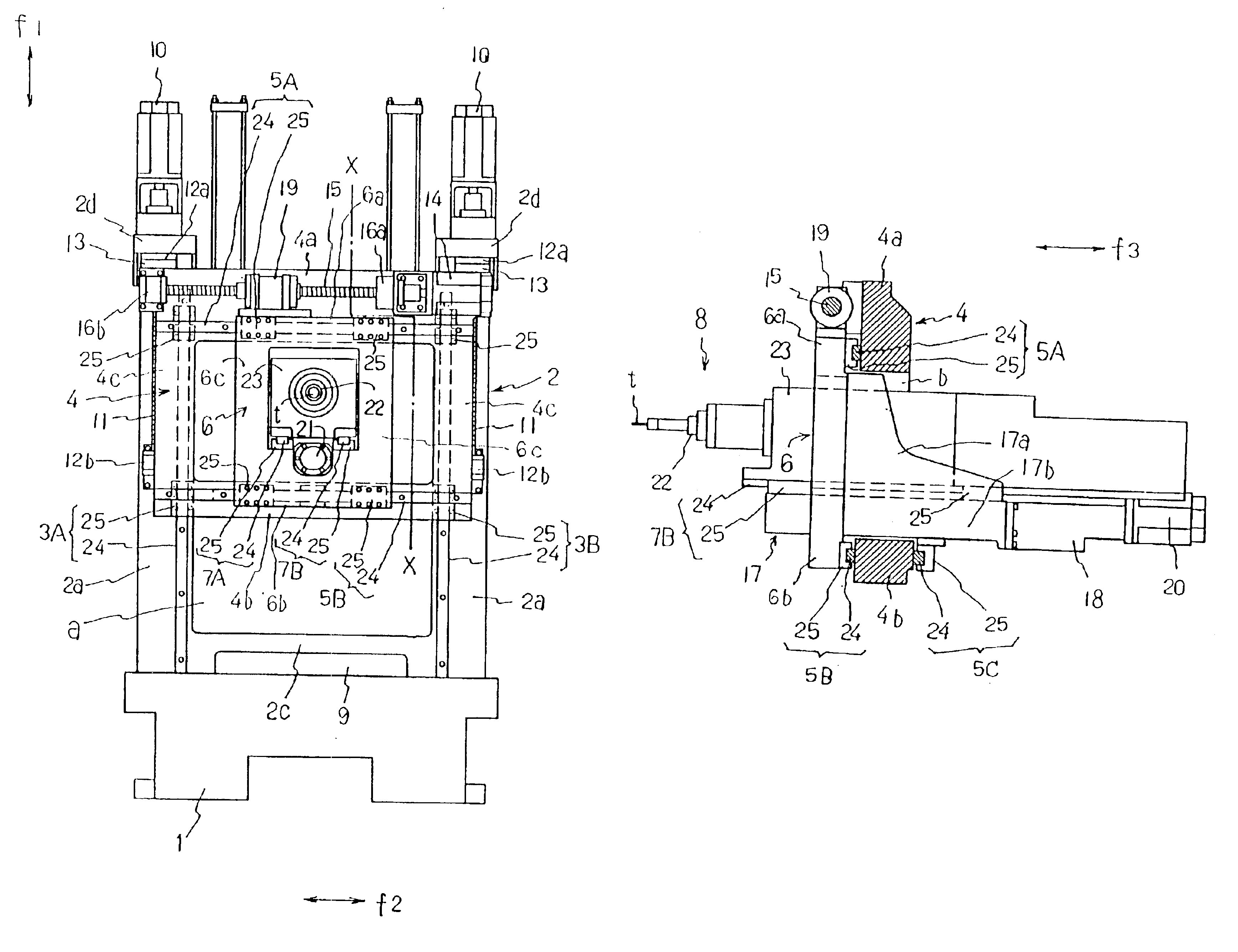
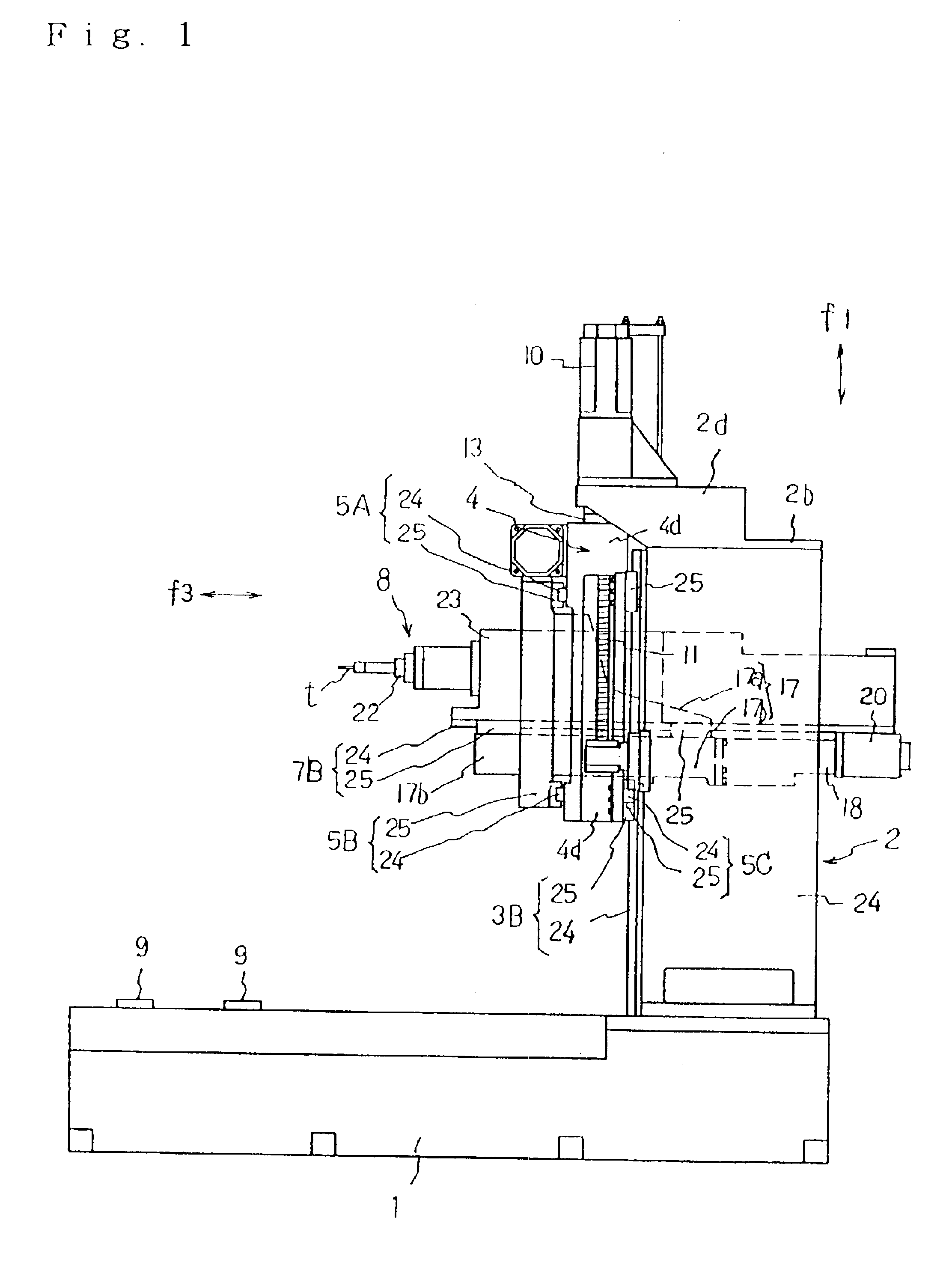
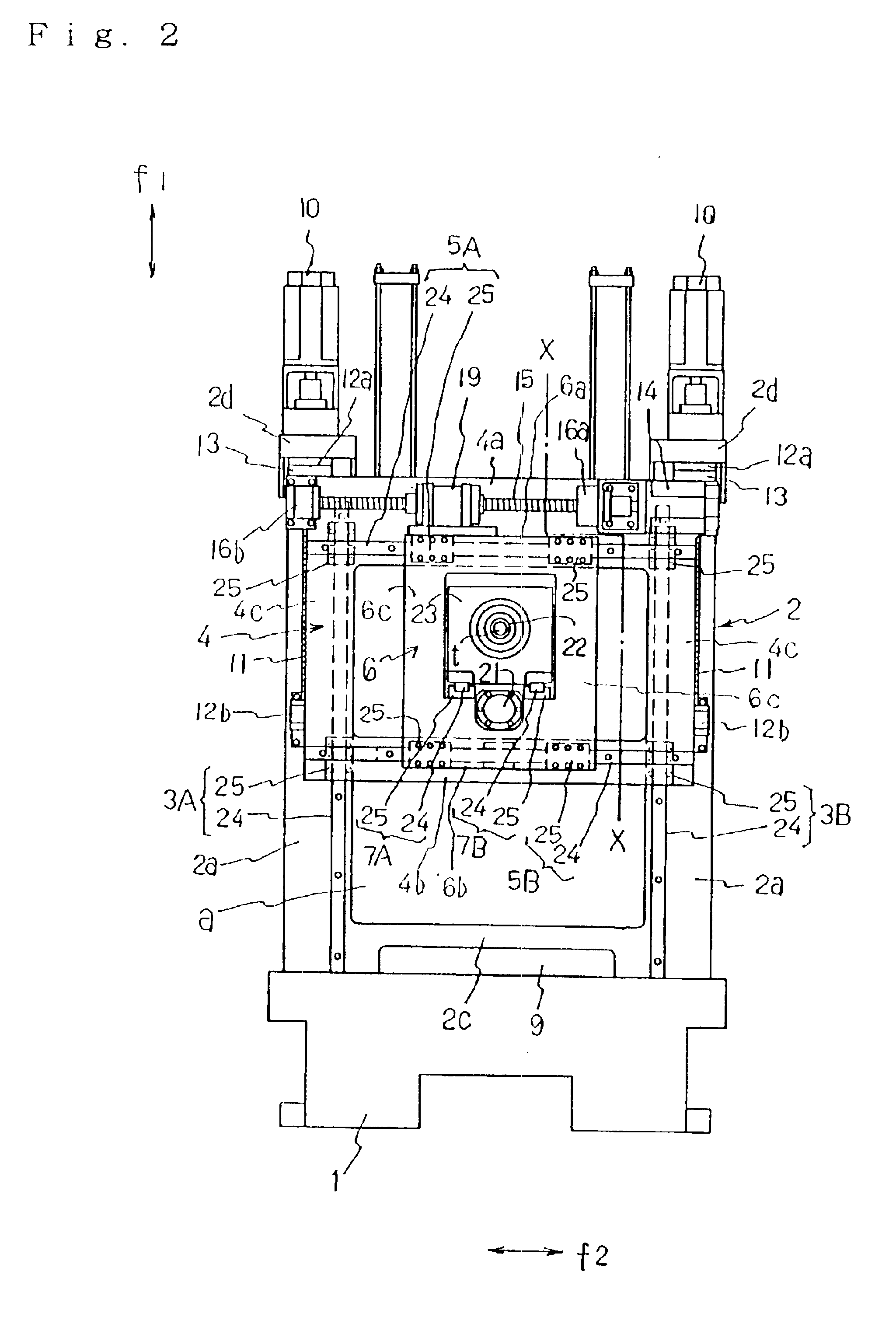
In this embodiment, a machine tool comprises a bed 1 forming the lowest part, a column 2 fixed on the upper surface of the bed 1, a first saddle 4 slidably-movably guided in vertical direction f1 through a pair of vertical guide route means 3A, 3B provided to the front surface of the column 2, a second saddle 6 slidably-movably guided in lateral direction f2 through a pair of lateral guide route means 6A, 5B, 5C provided to three positions of the front upper and lower positions and the rear lower position of the first saddle 4, and a spindle head 8 slidably-movably guided in longitudinal direction f3

The second saddle 6, as shown in FIGS. 4, 6, comprises one pair of right and left lateral parts 6a, 6b each having a rectangular cross-section and one pair of upper and lower vertical parts 6c, 6c each having a rectangular cross-section, consisting chiefly of a vertical rectangular frame body made of fettling steel having a l...


PUM

PropertyMeasurementUnit
widthaaaaaaaaaa
position stabilityaaaaaaaaaa
lengthaaaaaaaaaa

Abstract

A machine tool capable of performing an accurate machining by preventing a second saddle 6 from displacing aslant to suppress the vibrations of a spindle head 8, wherein a column 2 is fixedly installed on bed 1, a first saddle 4 is movably guided by the column 2 in vertical direction f1, a second saddle 6 is movably guided by the first saddle 4 in lateral direction f2, a spindle head 8 is movably guided by the second saddle 6 in longitudinal direction 18, and interfitted guide route devices 5A, 5B, 5C for guiding the second saddle 6 in lateral direction f2 are formed at the rear lower position of the first saddle 4 as well as at the front upper and lower positions of the first saddle 4.

Description

FIELD OF THE INVENTIONThe present invention relates to a machine tool increasing in position stability of a spindle.BACKGROUND OF THE INVENTIONA machine tool capable of shortening the length of spindle direction (longitudinal direction) of a first saddle, a second saddle and a column as well as speeding up the longitudinal feed of a spindle head, wherein the column is fixedly on a bed, the first saddle is movably guided by the column in vertical direction, the second saddle is movably guided by the first saddle in lateral direction, and the spindle head is movably guided by the second saddle in longitudinal direction, has been known (See Japanese Patent Provisional Publication No. 365529 of 1992, for example).In this machine tool, when the first saddle and the second saddle are moved in vertical and lateral direction or when the spindle head is moved in longitudinal direction, the second saddle is hard to attempt the position stability. Unless the second saddle has sufficient positi...

Claims


Application Information

Patent Timeline
Patent Type & Authority Patents(United States)
IPC IPC(8): B23Q1/25B23Q1/70B23Q11/00B23Q1/62B23Q1/26B23Q1/40B23Q5/40B23Q5/22B23Q1/00B23Q1/01B23Q1/56
CPCB23Q1/015B23Q1/017B23Q1/626Y10T409/309576Y10T409/307112Y10T409/304312Y10T408/91Y10T409/309744B23Q1/70
Inventor SUGATA, SHINSUKESEO, YOSHIHIDE
Owner HORKOS
Why Eureka
Try Eureka