Orthodontic bracket

a bracket and orthodontic technology, applied in the field of orthodontic brackets, can solve the problems of poor aesthetic appreciation, difficulty in handling, troublesome work for doctors, etc., and achieve the effect of increasing durability

Inactive Publication Date: 2005-01-18
TOMY CHOFU TOKIOTOKYO JP
View PDF19 Cites 53 Cited by
  • Summary
  • Abstract
  • Description
  • Claims
  • Application Information

AI Technical Summary

Benefits of technology

As the orthodontic bracket has the clip made of resin, complicated shapes can be easily obtained in comparison with the metal-made clip, and as the blank material itself has elasticity over a very broad range, the pressure of the archwire may be obtained t

Problems solved by technology

Furthermore, the orthodontic bracket 100 also obtains excellent effects that can solve following problems (i) to (ii) that are occurred when an elastomeric ligature ring is (not shown) is employed.(i) reduction of ligating force on the archwire owing to its permanent elongation; and(ii) discoloration by foods and drinks resulting poor aesthetic appreciation.
This problem similarly happens when using a

Method used


Image

  • Orthodontic bracket
  • Orthodontic bracket
  • Orthodontic bracket

Examples


Embodiment Construction

The embodiments according to the invention will be explained referring to the attached drawings. In each of the embodiments, a twin bracket is exemplified as the orthodontic bracket, but the invention is applicable to a single bracket, and is not limited to the twin bracket.

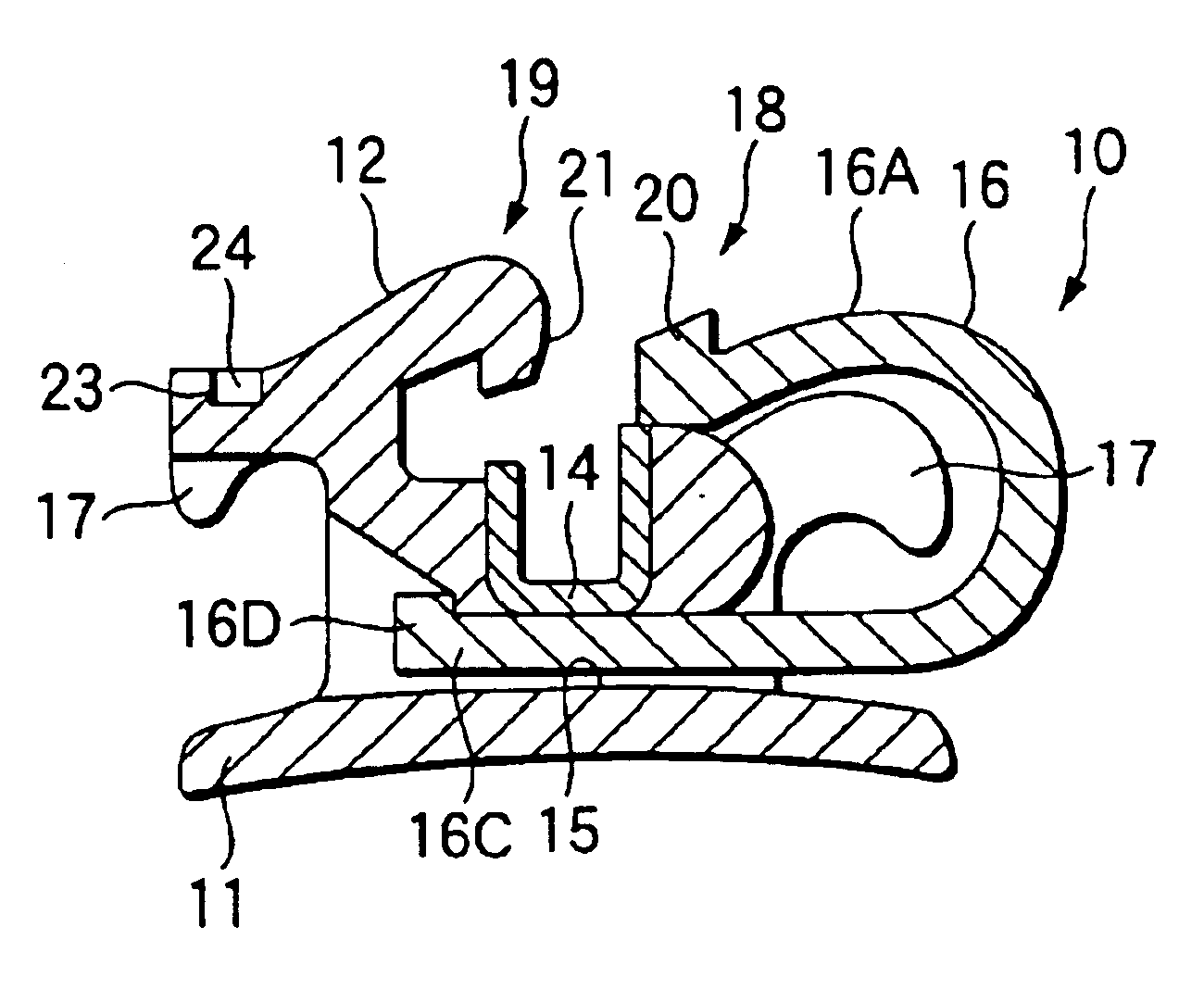
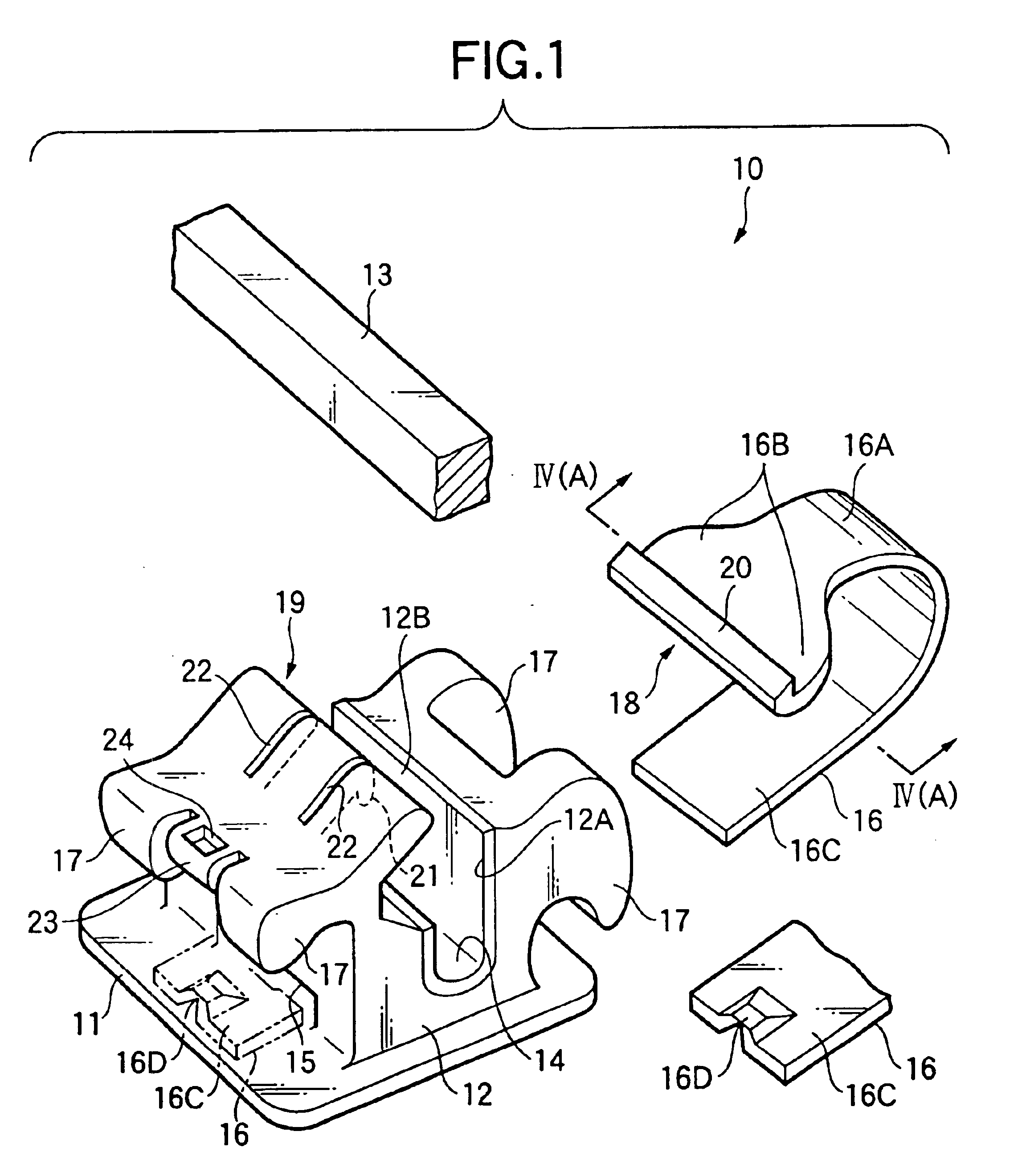
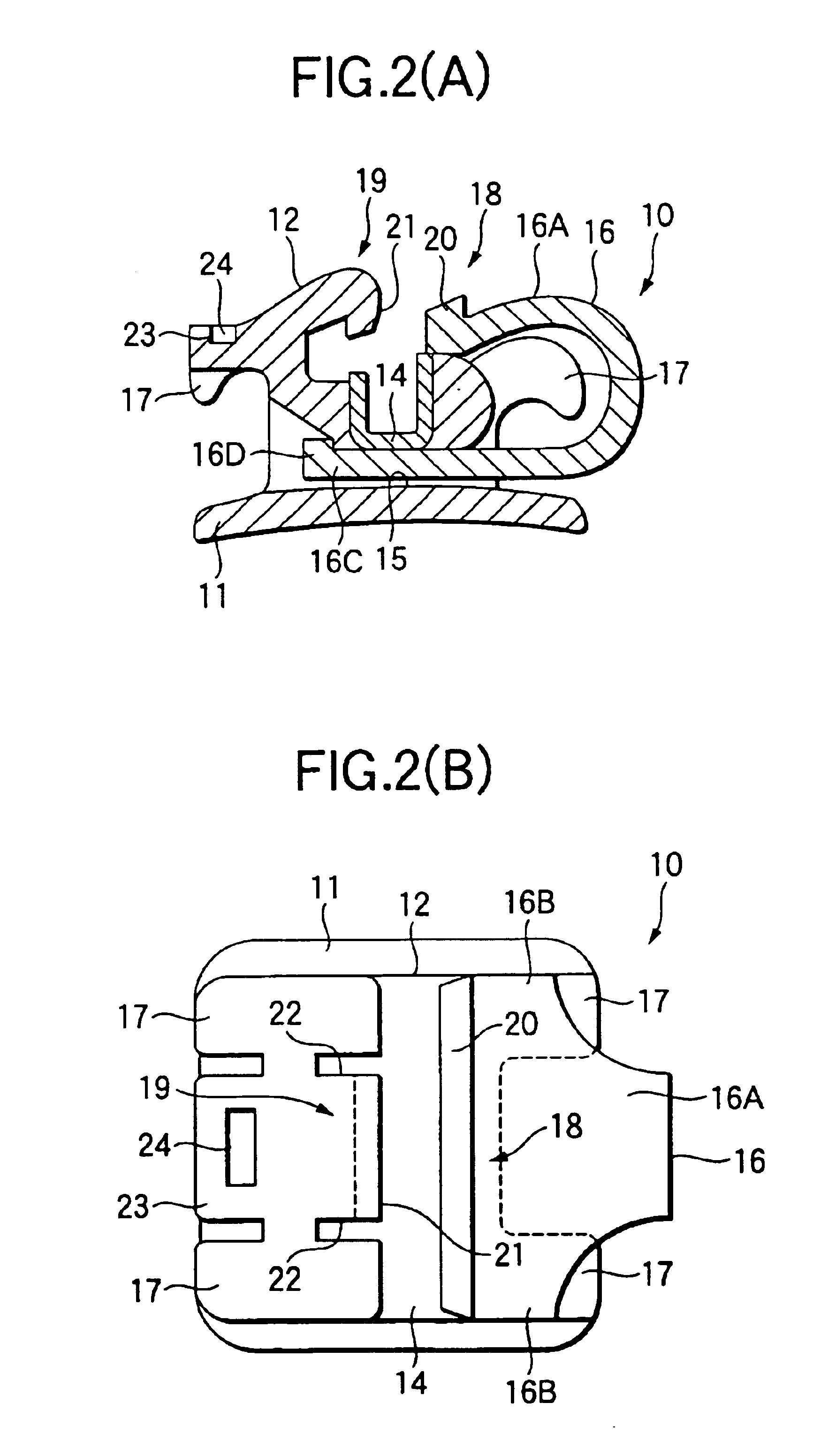
As seeing in FIG. 1, the orthodontic bracket 10 of a first embodiment according to a first aspect of the present invention is the twin bracket comprises, a mask-like base 11 attached to the enamel surface of a tooth, a bracket main body 12 furnished on the base 11 at its one side, a groove-like archwire slot 14 formed in the bracket main body 12 and rectangular in cross section for receiving the archwire 13, a guiding part 15 formed between the base 11 in the bracket main body 12 and an archwire slot 14, a band-like clip 16 guided in the guiding part 15, and four tie-wings 17 provided outside of the bracket main body 12.

The base 11 has a concaved spherical face corresponding to the tooth enamel surface and is to ...


PUM


Abstract

An orthodontic bracket enabling to securely maintain positive pressure of an archwire effecting to the bottom of an archwire slot even if doing the rotational control more than a determined amount. The orthodontic bracket has a base, a main body furnished on the base, an archwire slot formed in the main body, a guiding part crossing with the slot, and a band-like clip guided in the guiding part. A clip is curved in U-shape as covering at least one part of a reverse base side in the archwire slot, and a locking portion furnished at one end side in the length direction of the clip creeps under a cover portion supported by the main body. The locking claw formed in the locking portion and a covering claw formed in the cover portion get over and engage each other.

Description

BACKGROUND OF THE INVENTIONThe present invention relates to an orthodontic bracket, and in particular such an orthodontic bracket enabling to secure positive pressure effecting to an archwire received in an archwire slot for correcting irregularities of the teeth, and enabling to maintain the pressure for a long time.FIG. 14A shows an orthodontic bracket 100 correcting a row of teeth. The orthodontic bracket 100 comprises a mask-like base 101 attached to a enamel surface of tooth, a bracket main body 102 furnished on the base 101 at its one side, an archwire slot 103 formed in the bracket main body 102, a guiding part 104 formed at the base side 101 and penetrating in a transverse direction with the archwire slot 103, and a band-like clip 105 guided in the guiding part 104 (hereinafter defined as a prior art example 1).With respect to the orthodontic bracket 100, the clip 105 is curved in substantial U-shape as covering at least one part of a side (the upper part in FIG. 14A) opposi...

Claims


Application Information

Patent Timeline
IPC IPC(8): A61C7/28A61C7/00A61C7/14A61C7/30
CPCA61C7/287A61C7/28A61C7/141A61C7/145A61C7/30
Inventor ORIKASA, MASAAKI
Owner TOMY CHOFU TOKIOTOKYO JP
Why Eureka
Try Eureka