Electric connector for connecting electronic instruments

a technology of electronic instruments and electric connectors, which is applied in the direction of coupling contact members, fixed connections, coupling device connections, etc., can solve the problems of obstructing the miniaturization of the telephone, the position of the end of the coil deviating from the desired position,

Inactive Publication Date:
View PDF4 Cites 10 Cited by
  • Summary
  • Abstract
  • Description
  • Claims
  • Application Information

AI Technical Summary

Benefits of technology

An object of the present invention is to provide an electric conne

Problems solved by technology

However, there in a problem that when the coil spring is compressed, the position of the end of the coil deviates from a desired positio

Method used


Image

  • Electric connector for connecting electronic instruments
  • Electric connector for connecting electronic instruments
  • Electric connector for connecting electronic instruments

Examples


third embodiment

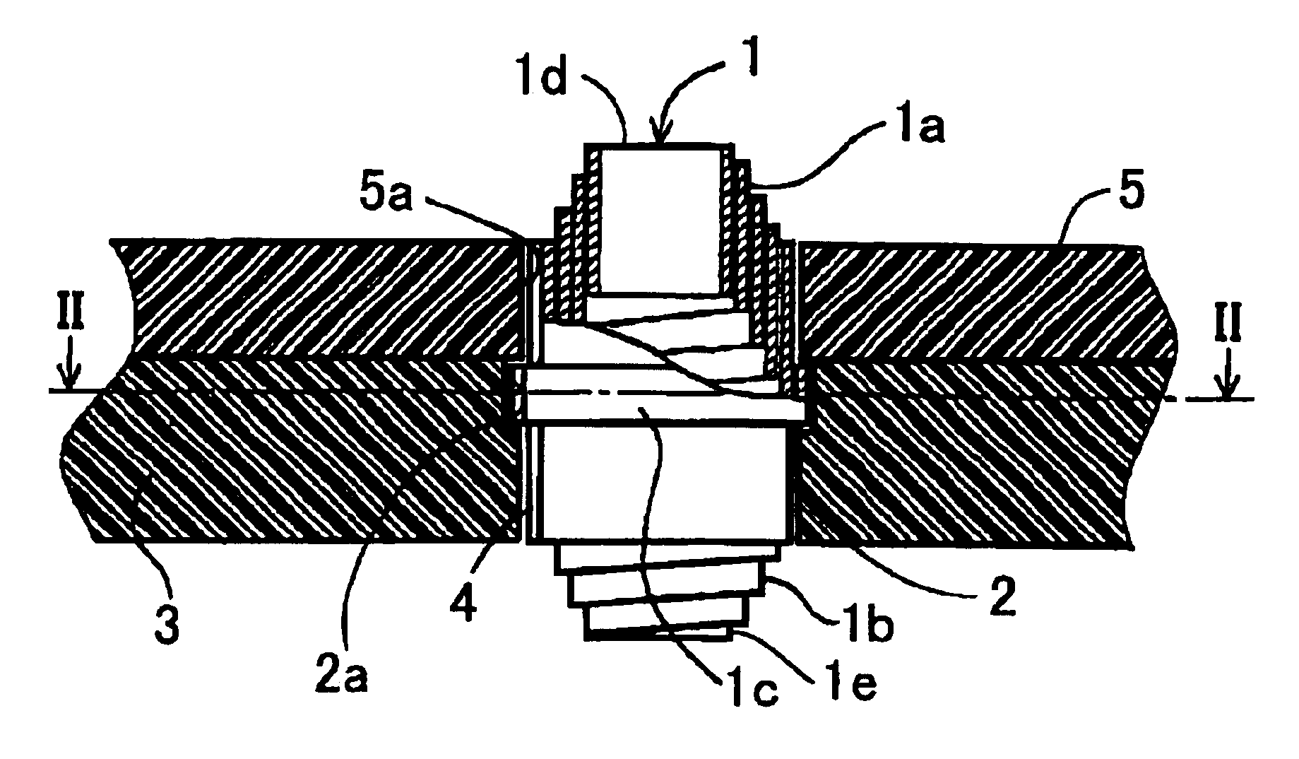
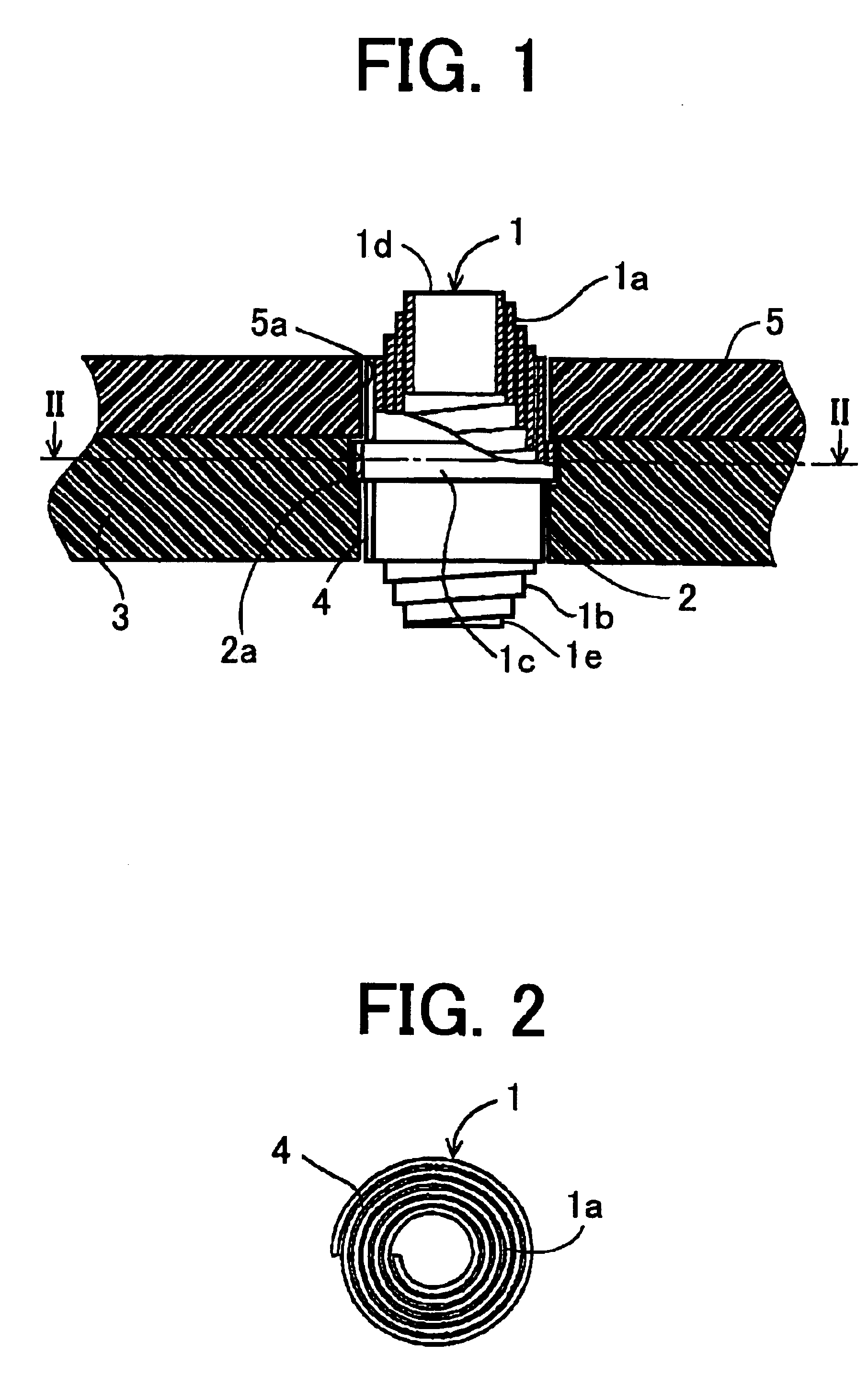
FIG. 7 is a side view showing a volute spring and FIG. 9 is a development of the volute spring. The same reference numerals as those of FIG. 1 are used in the figures so that detailed explanations are omitted.

A securing tab 21 is projected from the base cylinder 4 in the horizontal direction for securing the volute spring 1 to the frame 3. A triangular engaging projection 21a is formed on the tab 21.

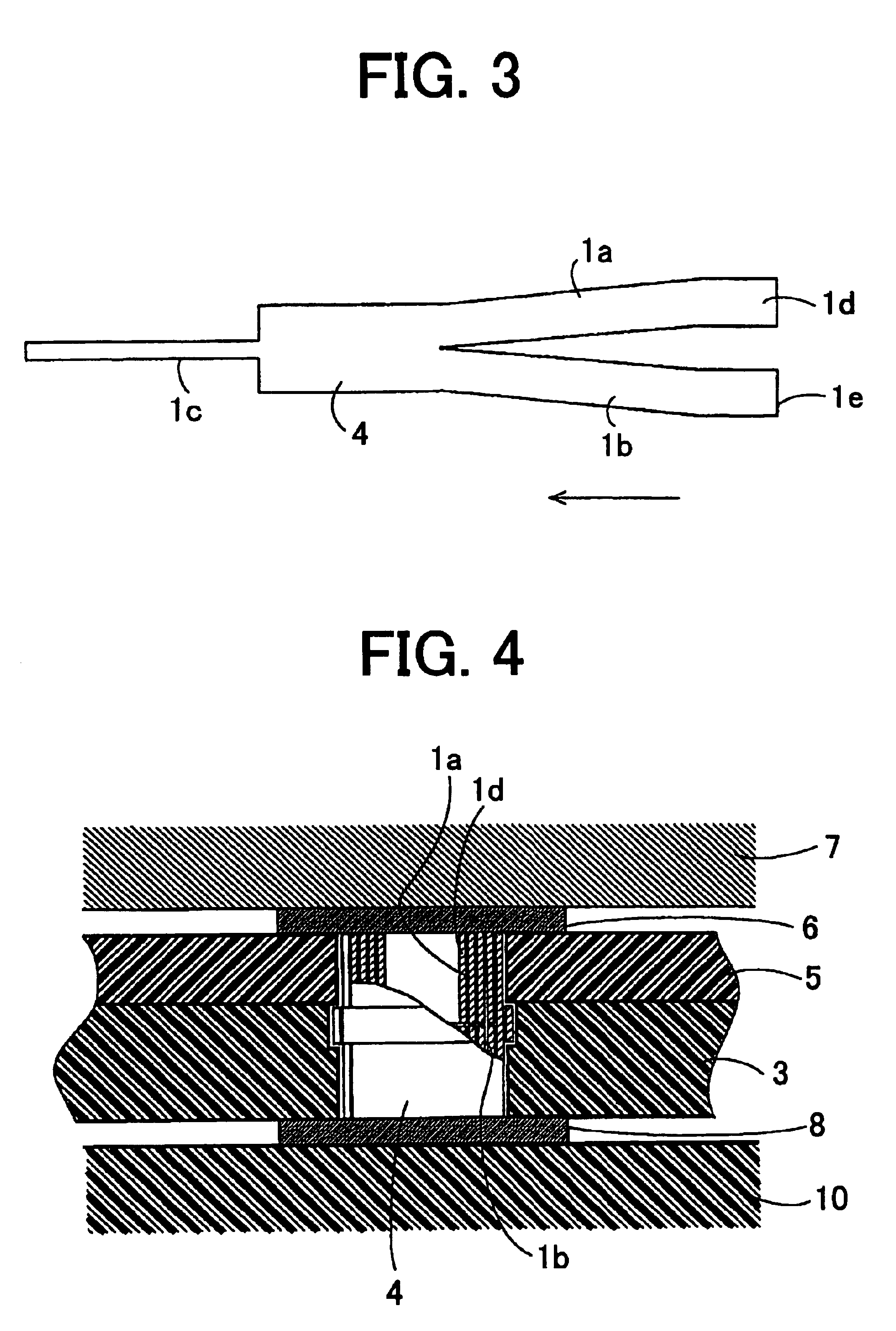
FIG. 10 is a plan view showing an insertion operation of the volute spring 1 in an electronic instrument, and FIG. 11 is a sectional view showing an inserted condition.

As shown in FIGS. 10 and 11, in a frame 22 made of resin, a pair of holes 23 are formed for the volute spring 1. As shown in FIG. 10, in each hole 23, a slit 24 is formed in a radial direction of the hole. The volute spring 1 is inserted in the hole 23, engaging the triangular engaging projection 21a with the inside wall of the hole 23. Thus, volute spring 1 is fixed to the frame 22. As shown in FIG. 11, the volute spring...


PUM


Abstract

An electric connector has a frame made of insulation, and a double-ended volute spring composed by an outermost base cylinder, and a pair of volute spring portions extending from the base cylinder so as to be contact with terminals of an electronic instrument. The base cylinder is secured in a hole formed in the frame.

Description

BACKGROUND OF THE INVENTIONThe present invention relates to an electric connector for an electronic instrument such as a portable telephone.In the portable telephone, a microphone is connected to terminals on a circuit substrate by electric connectors. In a conventional portable telephone, the microphone is connected to terminals by coil springs. The coil spring is compressed between a terminal of the microphone and a terminal of the substrate so as to connect both the terminals.However, there in a problem that when the coil spring is compressed, the position of the end of the coil deviates from a desired position. In order to ensure the connection, the terminal must be formed into a large size, which obstructs the miniaturization of the telephone.SUMMARY OF THE INVENTIONAn object of the present invention is to provide an electric connector which may exactly connect terminals at a mall connecting area.According to the present invention, there is provided an electric connector compri...

Claims


Application Information

Patent Timeline
IPC IPC(8): H01R13/24H01R13/22
CPCH01R13/2421H01R12/714H01R12/52H01R2201/16
Inventor KUWABARA, ATSUSHIOJIMA, TSUTOMU
Why Eureka
Try Eureka