
System and method of use for revascularizing stenotic bypass grafts and other occluded blood vessels

a technology of stenotic bypass grafts and occluded blood vessels, applied in the medical field, can solve problems such as the production of debris, and achieve the effects of effective revascularization, safe revascularization, and effective opening of the lumen

Inactive Publication Date: 2005-01-18
KENSEY NASH CORP
View PDF54 Cites 233 Cited by
  • Summary
  • Abstract
  • Description
  • Claims
  • Application Information

AI Technical Summary

Benefits of technology

It is another object of this invention to provide a system and methods for effectively revascularizing partially or totally occluded blood vessels and for removing any debris produced during the procedure from the patient's body.
The debris blocking member is located distally of the working head to prevent debris from flowing distally thereof.

Problems solved by technology

Some debris may be produced by the operation of the working head.

Method used


Image

  • System and method of use for revascularizing stenotic bypass grafts and other occluded blood vessels
  • System and method of use for revascularizing stenotic bypass grafts and other occluded blood vessels
  • System and method of use for revascularizing stenotic bypass grafts and other occluded blood vessels

Examples


Embodiment Construction

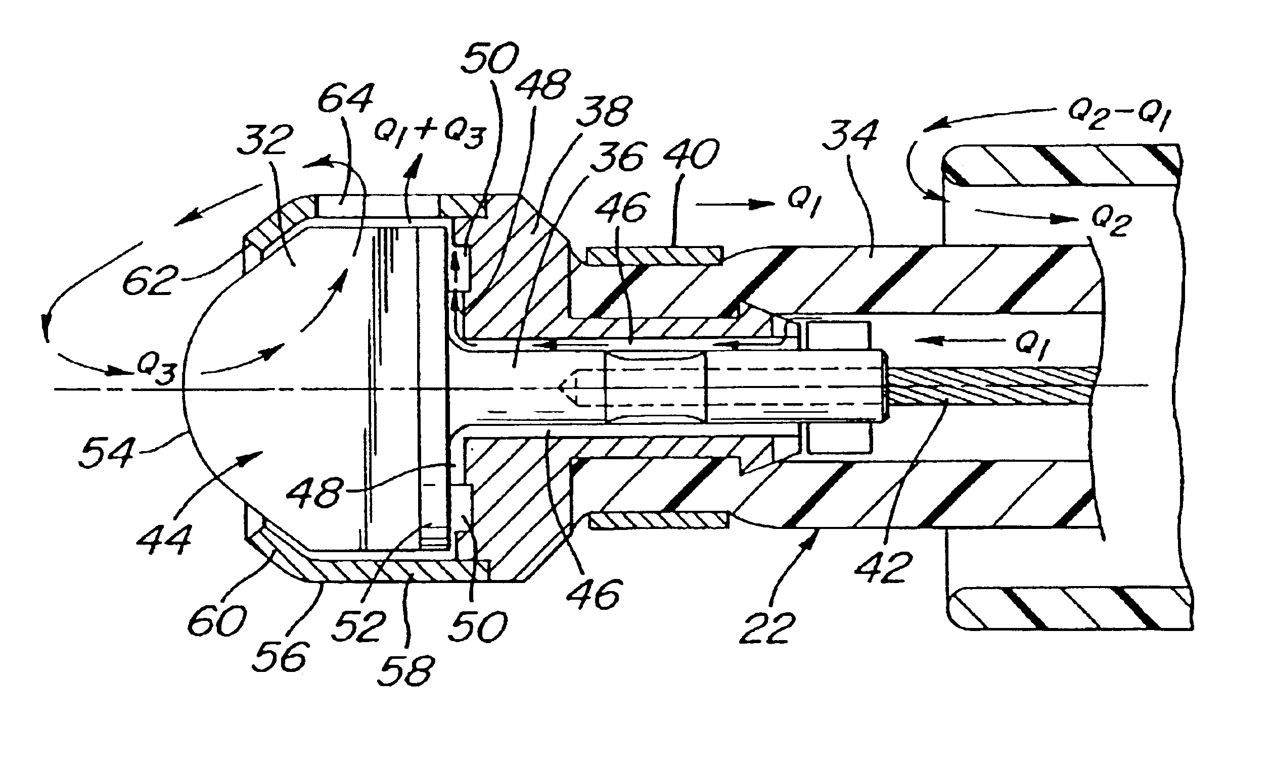
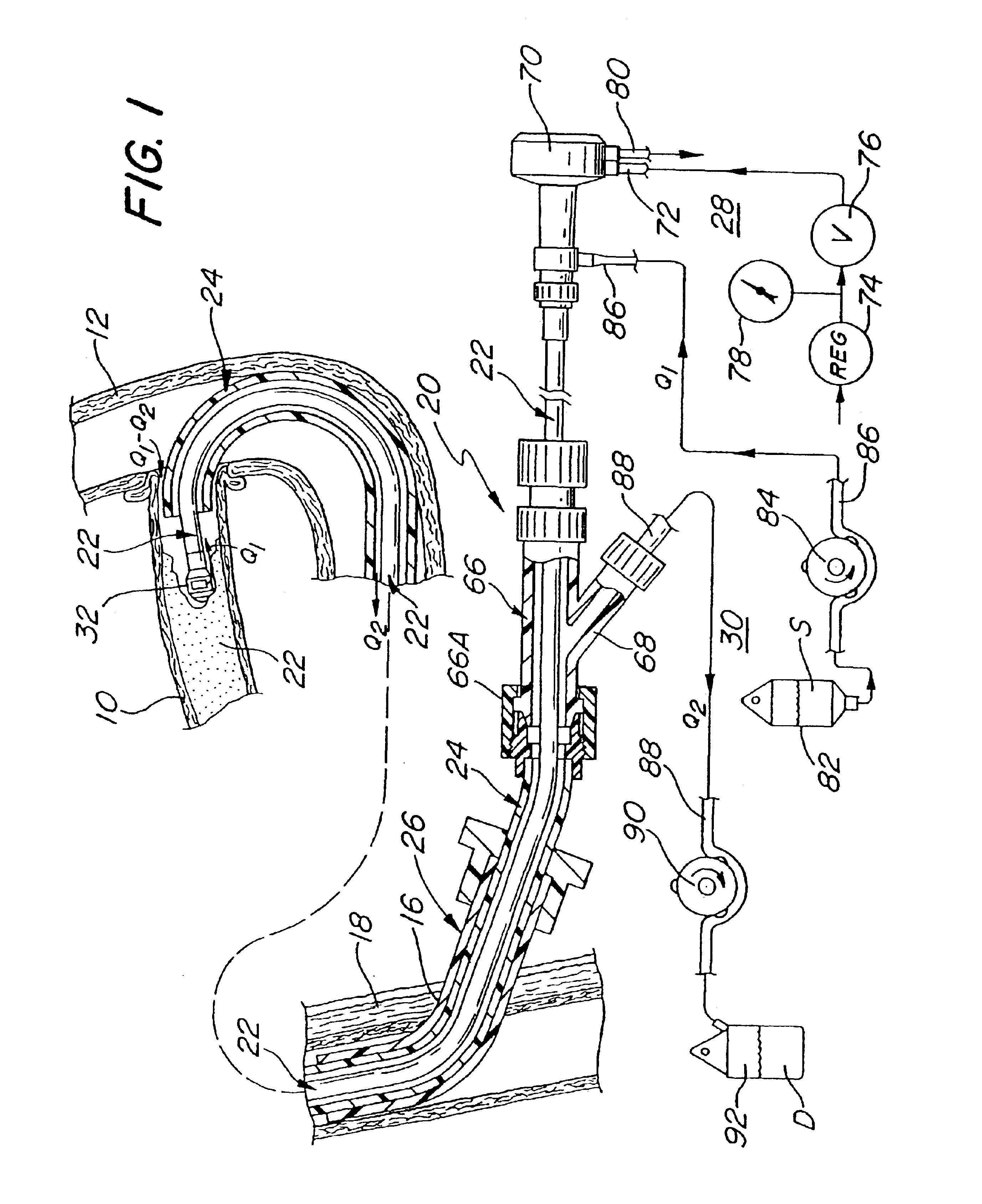
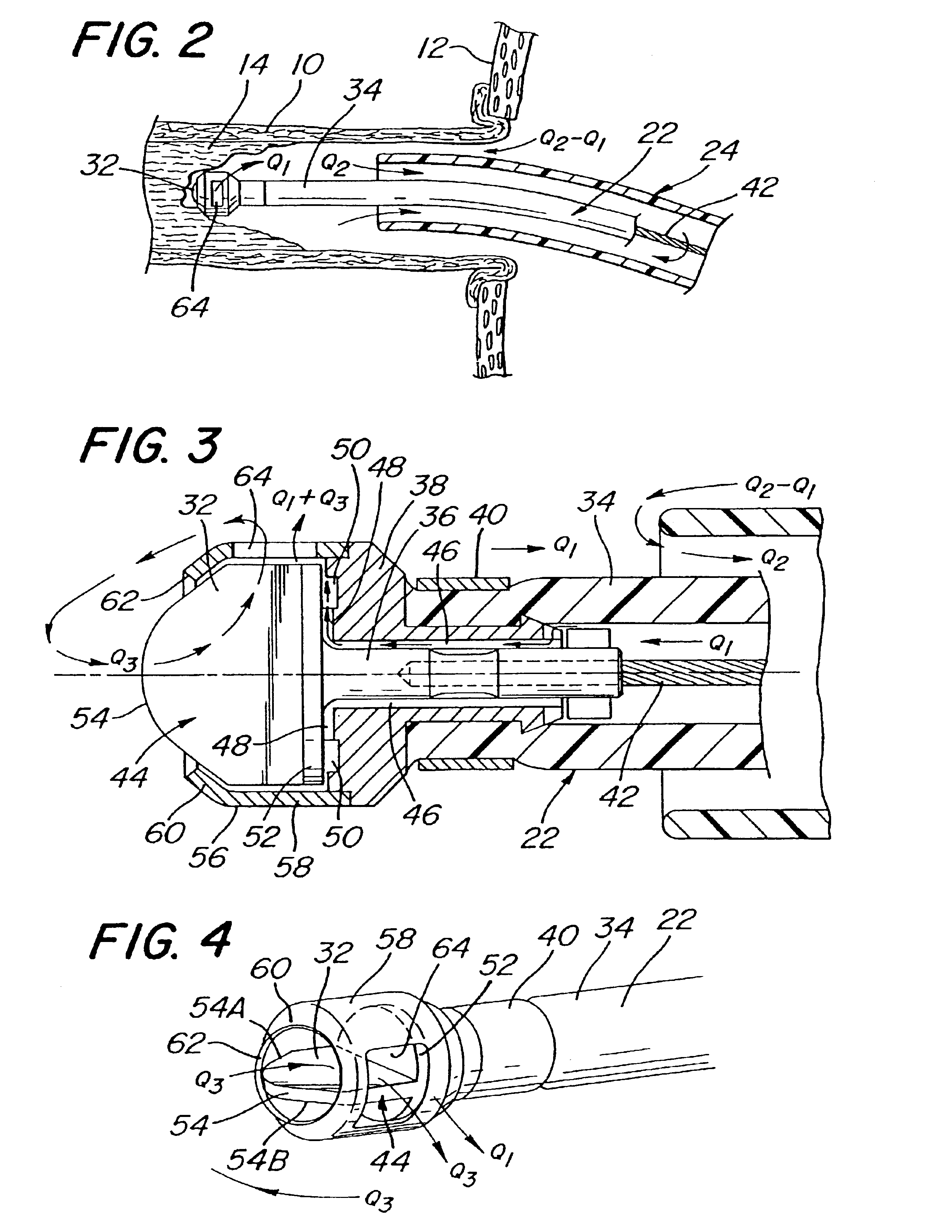
Referring now in greater detail to the various figures of the drawings wherein like reference characters refer to like parts, there is shown at 20 in FIG. 1 a system for revascularizing or opening a lumen through a coronary bypass graft which has become occluded, such as by the formation of a stenotic lesion or the build-up of plaque therein. As used herein the term “occluded” is given its broadest interpretation. Thus, an “occluded” graft or blood vessel may be either totally blocked or only partially blocked (i.e., there is a passageway or lumen through which some blood may flow).

The system 20 is arranged to be used for forming or enlarging a lumen through any blood vessel within the body of a living being, e.g., an occluded femoral artery downstream of the profunda femoris, not necessarily an occluded coronary bypass graft or an occluded coronary artery. In particular, the system 20 is arranged to produce a channel or lumen or to enlarge a lumen through the occlusive material wit...


PUM


Abstract

A system and method for opening a lumen in an occluded blood vessel, e.g., a coronary bypass graft, of a living being. The system comprises an atherectomy catheter having a working head, e.g., a rotary impacting impeller, and a debris extraction sub-system. The atherectomy catheter is located within a guide catheter. The working head is arranged to operate on, e.g., impact, the occlusive material in the occluded vessel to open a lumen therein, whereupon some debris may be produced. The debris extraction sub-system introduces an infusate liquid at a first flow rate adjacent the working head and withdraws that liquid and some blood at a second and higher flow rate, through the guide catheter to create a differential flow adjacent the working head, whereupon the debris is withdrawn in the infusate liquid and blood for collection outside the being's body. The introduction of the infusate liquid may also be used to establish an unbalanced flow adjacent the working head to enable the atherectomy catheter to be steered hydrodynamically. A guide wire having an inflatable balloon on its distal end may be used with the atherectomy catheter to block the flow of debris distally, while enabling distal tissues to be perfused with an oxygenating liquid. At least one flow control port may be provided in the guide catheter to prevent collapse of the vessel being revascularized. A cradle is provided to fix the guide catheter and guide wire in position within the body of the being while enabling the atherectomy catheter to be advanced along the guide wire and through the guide catheter.

Description

BACKGROUND OF THE INVENTIONThis application relates generally to medical instruments and methods of use to remove occlusive material from a vessel, duct or lumen within the body of a living being.Catheter instruments have been suggested or disclosed in the patent literature for effecting non-invasive or minimally invasive revascularization of occluded arteries. For example, in U.S. Pat. No. 4,445,509 there is disclosed a recanalization catheter designed specifically for cutting away hard, abnormal deposits, such as atherosclerotic plaque, from the inside of an artery, while supposedly preserving the soft arterial tissue. That recanalizing catheter includes a sharp-edged, multi-fluted, rotating cutting tip mounted at the distal end of the catheter and arranged to be rotated by a flexible drive shaft extending down the center of the catheter. The rotation of the cutting head is stated as producing a “differential cutting” effect, whereupon relatively hard deposits are cut away from re...

Claims


Application Information

Patent Timeline
IPC IPC(8): A61B17/22A61B17/32A61D1/02A61D1/00A61M31/00A61F2/06A61M1/00A61M29/02
CPCA61B17/22A61B17/32037A61B17/320758A61B2017/22048A61B2017/22067A61B2017/320775A61M2205/05A61B2217/007A61M1/0058A61M1/0084A61M5/14232A61M2025/1095A61B2217/005A61M1/85A61M1/77A61B17/3203
Inventor NASH, JOHN E.FISHER, WILLIAM T.DODSON, JR., CHARLES W.
Owner KENSEY NASH CORP
Learn More