System and method of use for revascularizing stenotic bypass grafts and other blood vessels

a technology of stenotic bypass grafts and blood vessels, applied in the medical field, can solve the problems of reoccurring grafts, significant percentage of bypass surgical grafts, and limited use,

Inactive Publication Date: 2010-11-16
KENSEY NASH CORP
View PDF96 Cites 53 Cited by
  • Summary
  • Abstract
  • Description
  • Claims
  • Application Information

AI Technical Summary

Benefits of technology

[0017]It is another object of this invention to provide a system and methods for effectively revascularizing partially or totally occluded blood vessels and for removing any debris produced during the procedure from the patient's body.
[0026]The debris extraction means is arranged to introduce an infusate liquid at a first flow rate into the vessel adjacent the working head and to withdraw that liquid and some blood at a second and higher flow rate from the vessel. This action creates a differential flow in the vessel, whereupon debris within the vessel which is produced by the action of the working head on the occlusion material is positively withdrawn with the infusate liquid and blood from the vessel for remote collection, e.g., in a collection vessel located outside the body of the person being treated. Thus, the differential flow serves to prevent the debris from flowing into adjacent blood vessels, e.g., the aorta.

Problems solved by technology

However, their use is limited to some very selected applications.
Unfortunately a significant percentage of bypass surgical grafts become re-occluded over time.
Where, however, the graft is totally occluded balloon angioplasty in unavailable.
As is known to those skilled in the art, one problem with a rotary atherectomy device is that unless the debris produced is so small and benign that it can be left within the patient's vascular system there must be some means to ensure that the debris does not flow upstream into the aorta during the procedure or into the downstream artery graft at the break-through point when the device comes out the distal side of a total occlusion, since either action could present a significant hazard to the patient.
In particular, the former route risks stroke, and the later route risks local ischemia of heart muscle when debris blocks off small arteries.
While the balancing of the infusion and aspiration flow rates to minimize blood loss may be desirable, such action does not insure positive removal of all debris produced during the revascularization procedure.

Method used


Image

  • System and method of use for revascularizing stenotic bypass grafts and other blood vessels
  • System and method of use for revascularizing stenotic bypass grafts and other blood vessels
  • System and method of use for revascularizing stenotic bypass grafts and other blood vessels

Examples


Embodiment Construction

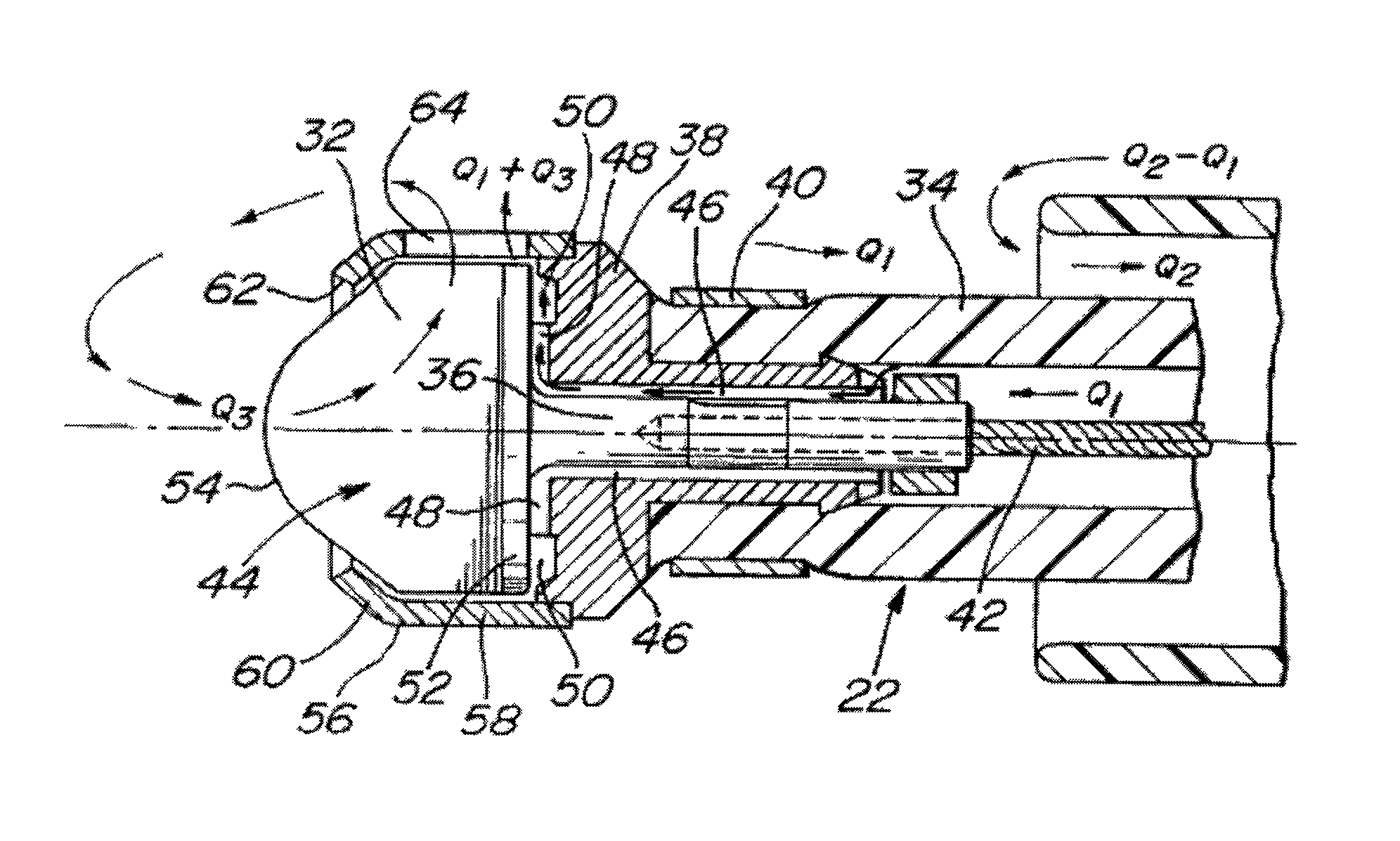
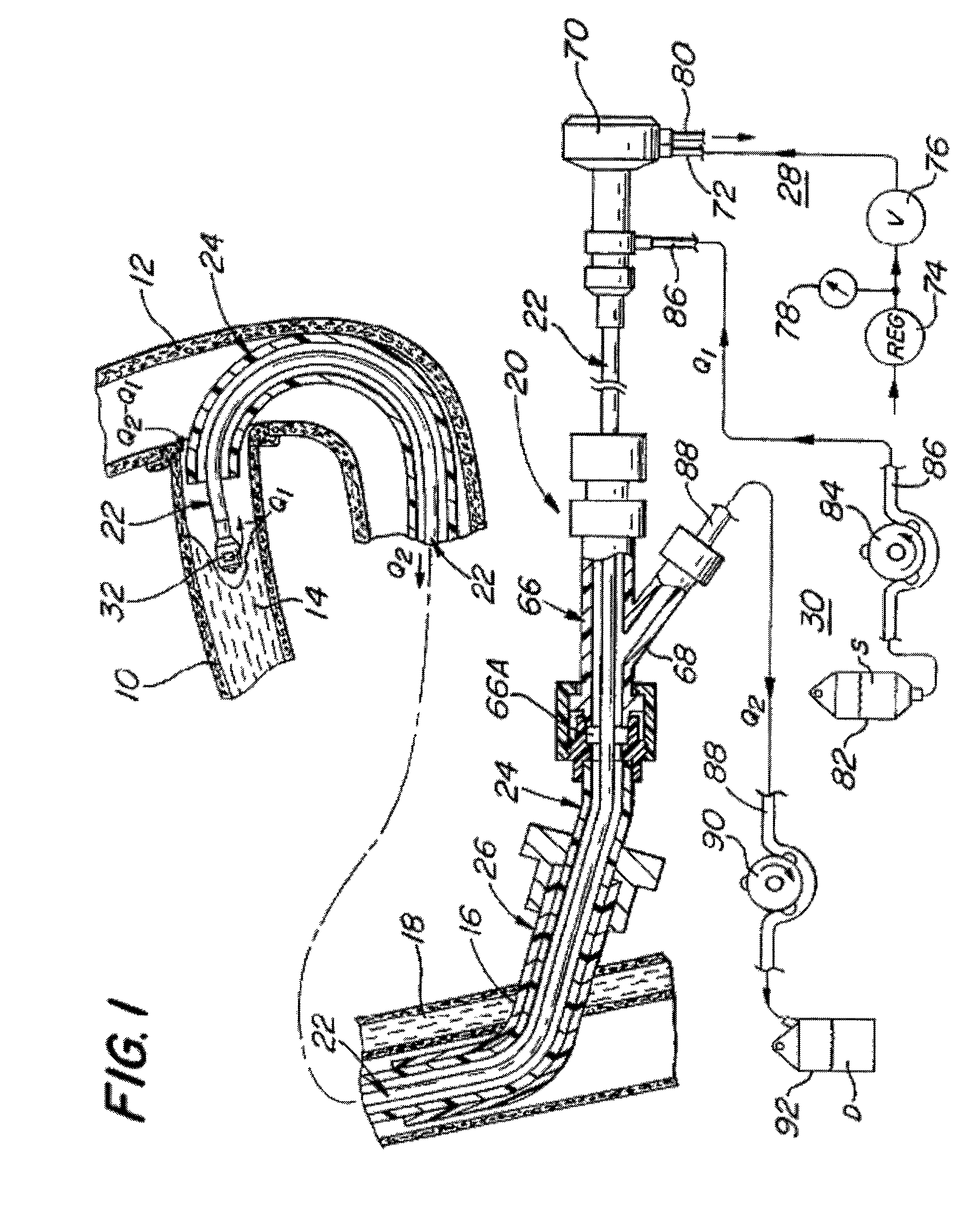
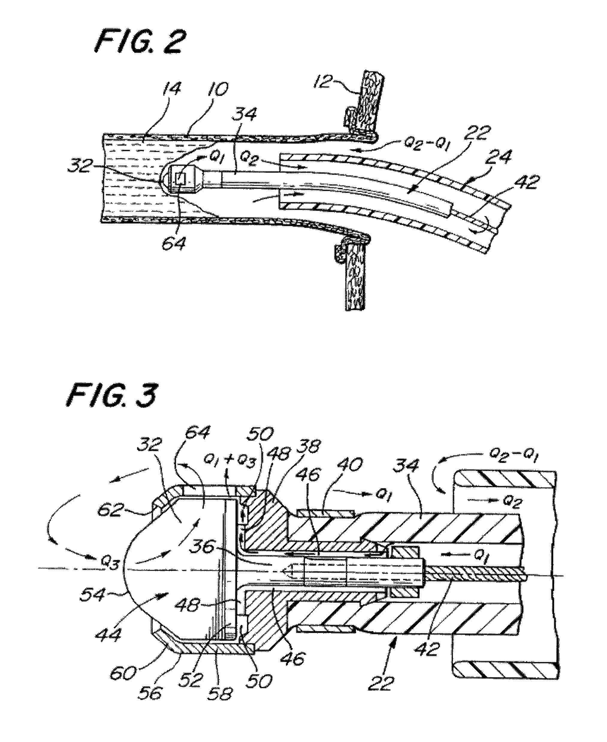
[0033]Referring now in greater detail to the various figures of the drawings wherein like reference characters refer to like parts, there is shown at 20 in FIG. 1 a system for revascularizing or opening a lumen through a coronary bypass graft which has become occluded, such as by the formation of a stenotic lesion or the build-up of plaque therein. As used herein the term “occluded” is given its broadest interpretation. Thus, an “occluded” graft or blood vessel may be either totally blocked or only partially blocked (i.e., there is a passageway or lumen through which some blood may flow).

[0034]The system 20 is arranged to be used for forming or enlarging a lumen through any blood vessel within the body of a living being, e.g., an occluded femoral artery downstream of the profunda femoris, not necessarily an occluded coronary bypass graft or an occluded coronary artery. In particular, the system 20 is arranged to produce a channel or lumen or to enlarge a lumen through the occlusive ...


PUM


Abstract

A system and method for opening a lumen in an occluded blood vessel, e.g., a coronary bypass graft, of a living being's vascular system. The system introduces an infusate liquid at a first flow rate to the occluded portion of the blood vessel, and withdraws that liquid and some blood at a second and higher flow rate. This action creates a differential flow in the occluded blood vessel portion and thereby prevent particles of occlusive material from flowing into any upstream blood vessel or downstream blood vessel in said living being's vascular system.

Description

CROSS REFERENCE TO RELATED APPLICATIONS[0001]This application is a continuation of application Ser. No. 10 / 665,337 filed Sep. 18, 2003, entitled System and method of Use for Agent Delivery and Revascularizing of Grafts and Vessels, now pending, which is a continuation of application Ser. No. 10 / 121,192, filed Apr. 12, 2002, now U.S. Pat. No. 6,905,505, which is a continuation of application Ser. No. 09 / 594,131, filed on Jun. 14, 2000, now U.S. Pat. No. 6,524,323, which is a continuation of U.S. patent application Ser. No. 09 / 233,712, filed on Jan. 19, 1999, now U.S. Pat. No. 6,080,170, which is a continuation-in-Part of U.S. patent application Ser. No. 08 / 900,598, filed on Jul. 25, 1997, now U.S. Pat. No. 5,879,361, which in turn is a continuation-in-part of U.S. application Ser. No. 08 / 690,438, filed on Jul. 26, 1996, now U.S. Pat. No. 5,779,721, all of which are assigned to the same assignee as this invention, and whose disclosures are incorporated by reference herein.FIELD OF THE...

Claims


Application Information

Patent Timeline
Patent Type & Authority Patents(United States)
IPC IPC(8): A61B17/22A61B17/32A61D1/02A61F2/06A61M1/00A61M29/02A61M31/00
CPCA61B17/22A61B17/32037A61B17/320758A61B2017/22048A61B2017/22067A61B2017/320775A61B2217/005A61B2217/007A61M1/0058A61M1/0084A61M5/14232A61M2025/1095A61M2205/05A61M1/85A61M2210/12A61M1/74A61M1/80
Inventor NASH, JOHN E.
Owner KENSEY NASH CORP
Why Eureka
Try Eureka