Slidably movable member and method of producing same

a movable member and sliding technology, applied in the field of sliding movable members, can solve the problems of inability to maintain and unsuitable wear performance, and achieve the effects of effective overturning drawbacks, low friction characteristics, and high wear resistan

Inactive Publication Date: 2005-01-18
NISSAN MOTOR CO LTD +1
View PDF33 Cites 54 Cited by
  • Summary
  • Abstract
  • Description
  • Claims
  • Application Information

AI Technical Summary

Benefits of technology

[0008]It is an object of the present invention to provide an improved slidably movable member which can effectively overcome drawbacks encountered in conventional slidably movable members which are used in contact with lubricating oil.
[0009]Another object of the present invention is to provide an improved slidably movable member which is high in wear resistance even in a

Problems solved by technology

However, it has been revealed, as a problem, that the slidably movable member coated with the hard carbon-based film is generally equal in low friction characteristics to other slidably movable members coated with hard films having no solid lubricating characteristics, such as those formed by ion plating of titanium nitride (TiN) or chromium nitride (CrN).
In other words, it has been revealed, as a problem, that the slidably movable member coated with the conventional carbon-based film is generally equal in low friction characteristics in lubricating oil to slidably movable members coated

Method used


Image

  • Slidably movable member and method of producing same
  • Slidably movable member and method of producing same
  • Slidably movable member and method of producing same

Examples


example 1

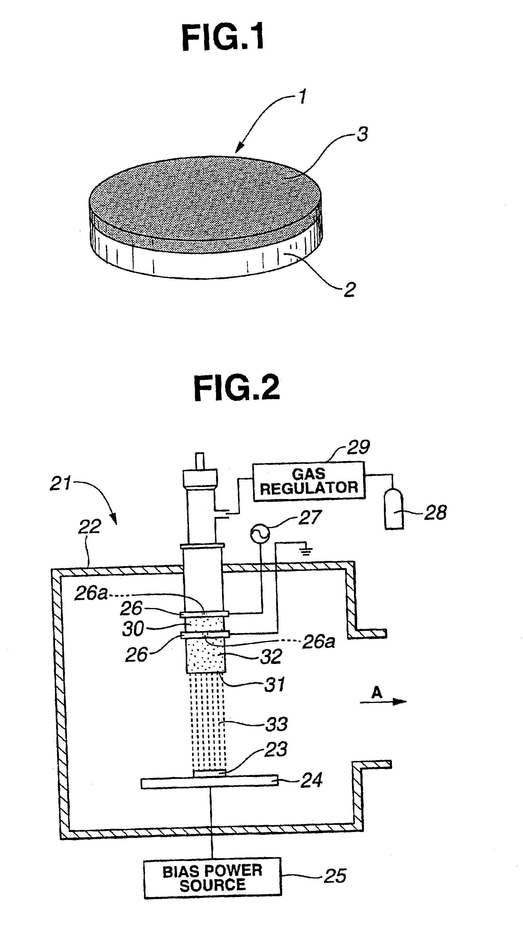
[0032]First, a disc-shaped substrate 2 made of ceramic (silicon nitride) was prepared to have a dimension of a 30 mm diameter and a 4 mm thickness, as shown in FIG. 1. A diamond polycrystal film (synthesized in gas phase) having a thickness of 10.0 μm was deposited on an upper surface of the substrate 2 by a thermal CVD process to form a hard carbon-based film 3 as shown in FIG. 1. The surface section of the hard carbon-based film 3 was estimated to contain hydrogen in an amount less than 10 at %. Subsequently, the surface of the diamond polycrystal film or hard carbon-based film 3 was ground to be finished by a diamond wheel or abrasive grain thereby obtaining a surface roughness Ra of 0.05 μm. As a result, a sidably movable member 1 as shown in FIG. 1 was produced.

example 2

[0033]First, a disc-shaped substrate 2 made of carburized steel (SCM415, chromium molybdenum steel, according to JIS G 4105) was prepared to have a dimension of a 30 mm diameter and a 4 mm thickness, as shown in FIG. 1. A super finishing was made on the upper surface of the substrate 2 to have a surface roughness Ra of 0.04 μm. Thereafter, a hard carbon-based film 3 was coated on the upper surface of the substrate 2 by an ion plating process using carbon ion beam, as shown in FIG. 1. The surface section of the hard carbon-based film 3 was estimated to contain hydrogen in an amount less than 10 at %. As a result, a slidably movable member 1 as shown in FIG. 1 was produced to have a surface roughness Ra of 0.09 μm without being subjected to finishing after formation of the hard carbon-based film 3.

example 3

[0034]A slidably movable member 1 of Example 3 was produced similarly to Example 2 with the exception that lapping was made on the upper surface of the slidably movable member 1 so that the slidably movable member has a surface roughness Ra of 0.03 μm.


PUM

PropertyMeasurementUnit
Lengthaaaaaaaaaa
Lengthaaaaaaaaaa
Thicknessaaaaaaaaaa

Abstract

A slidably movable member such as an adjusting shim used in a valve operating mechanism of an internal combustion engine of an automotive vehicle. The slidably movable member is used in contact with lubricating oil and comprises a substrate. A hard carbon-based film is coated on a surface of the substrate. The hard carbon-based film has a surface section which contains at least one of nitrogen and oxygen in an amount ranging from 0.5 to 30 at % and/or hydrogen in an amount of not more than 10 at %.

Description

BACKGROUND OF THE INVENTION[0002]This invention relates to improvements in a slidably movable member having a hard carbon-based film which is low in friction, and more particularly to the slidably movable member having the hard carbon-based film suitable to be used in a condition to be in contact with engine lubricating oil, transmission oil or the like.[0003]Hitherto, formation of hard carbon-based films have been proposed and put into practical use. The hard carbon-based films are formed of carbon-based materials such as amorphous carbon (a-C), a hydrogen-containing amorphous carbon (a-C:H), i-carbon (i-C) and diamond like carbon (DLC). The carbon-based films are usually formed by a plasma enhanced chemical vapor deposition (CVD) process in which hydrocarbon gas is plasma-decomposed to form the carbon-based film, or by an ion beam vapor deposition process using carbon and hydrocarbon ions. The thus formed carbon-based film has a high surface hardness and a high surface smoothness,...

Claims


Application Information

Patent Timeline
IPC IPC(8): F16C33/04F01L1/20F16C33/12F01L1/14C23C16/27F16H53/06
CPCF01L1/143F01L1/205F16C33/043F01L2101/00F01L2810/02Y10T403/32737Y10T428/30Y10T428/24355Y10T428/265Y10T428/24364Y10T428/24983Y10T428/24628Y10T292/096F01L2301/00
Inventor MIYAKE, SHOJIROYASUDA, YOSHITERUKANO, MAKOTOMABUCHI, YUTAKA
Owner NISSAN MOTOR CO LTD
Why Eureka
Try Eureka