Recessed resin tips used in a connecting method

a technology of resin tips and connecting methods, which is applied in the direction of connection insulation, connection contact material, cable junctions, etc., can solve the problems of bending, disconnection of conductive wires, and deterioration of insulation effects

Inactive Publication Date: 2005-01-18
YAZAKI CORP
View PDF20 Cites 24 Cited by
  • Summary
  • Abstract
  • Description
  • Claims
  • Application Information

AI Technical Summary

Benefits of technology

Under the circumstances, it is therefore an object of the present invention to provide a connecting method of connecting covered wires with each other, by which it is possible to prevent the molten insulating covers from being pushed out of the resin tips. Further, it is another object of the invention to provide resin tips which are appropriate in connecting the covered wires in accordance with the above method.

Problems solved by technology

1B), thereby causing the deterioration of insulation effect, the disconnection of conductive wire, the deterioration of bending, etc.
Therefore, also in this case, there may be caused problems of the deterioration of insulation effect of the cover 9 at a part of the ground wire W2, the disconnection of the core line 15 and the deterioration of bending, too.

Method used


Image

  • Recessed resin tips used in a connecting method
  • Recessed resin tips used in a connecting method
  • Recessed resin tips used in a connecting method

Examples


Embodiment Construction

Embodiments of the present invention will be described with reference to the drawings.

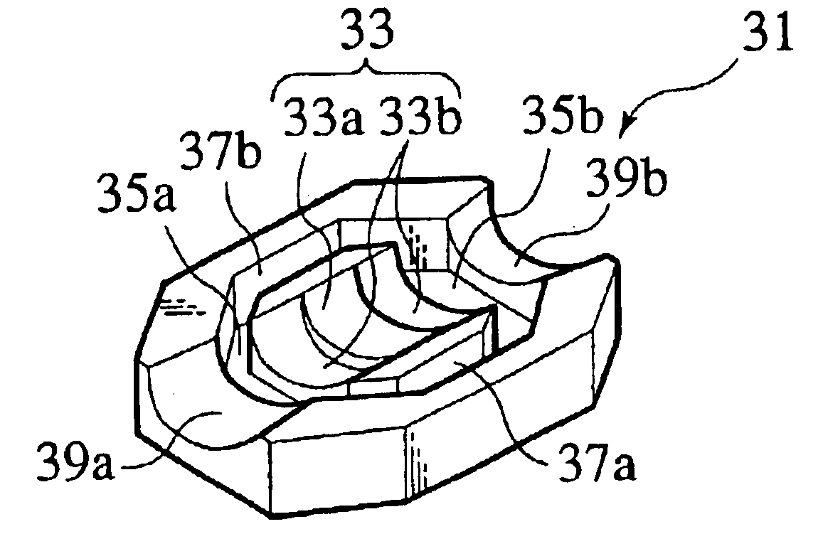
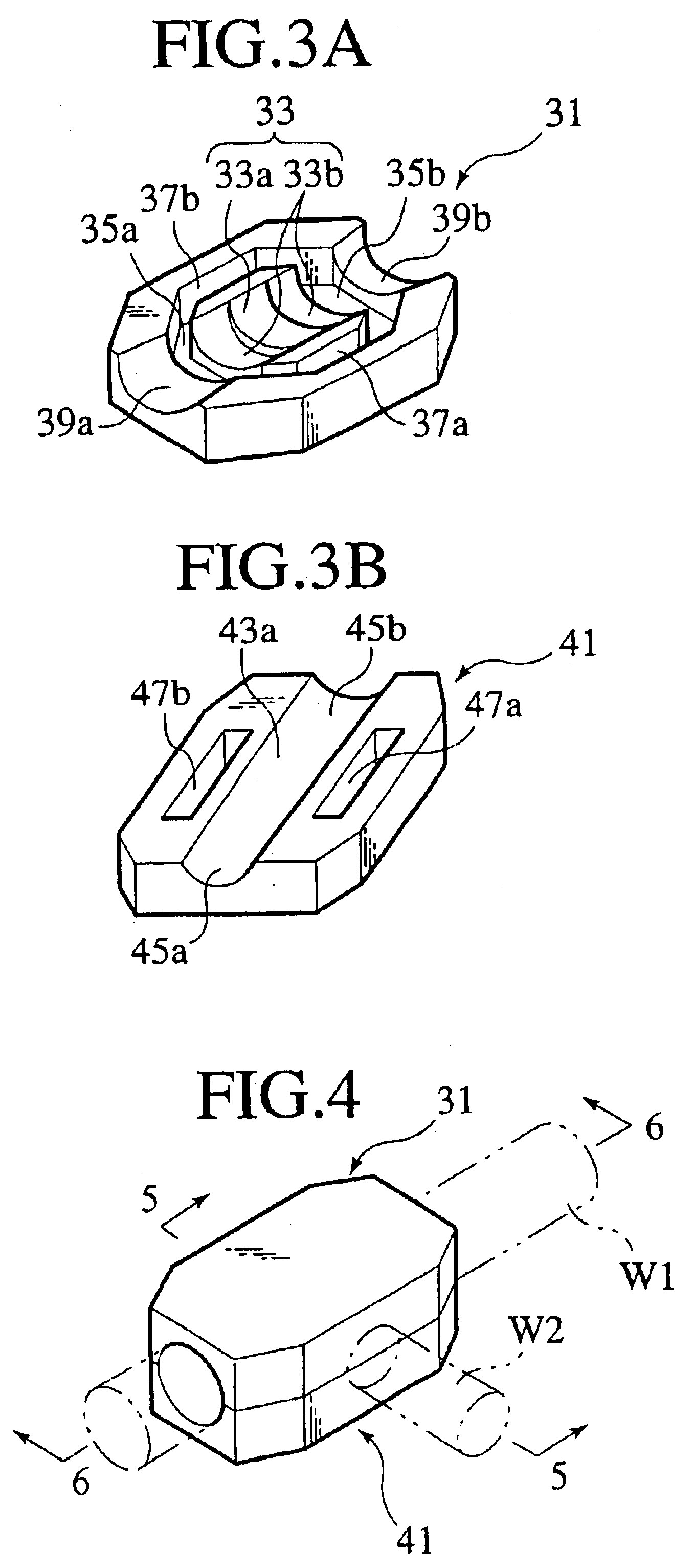
FIGS. 3A and 3B shows upper and lower resin tips in accordance with the first embodiment. FIG. 3A is a perspective view of the upper resin tip showing its recessed face directing upward. FIG. 3B is a perspective view of the lower resin tip showing its recessed face directing upward.

The upper resin tip 31 has a welding part 33 formed at its intermediate portion. The welding part 33 includes a semicircular-shaped recessed part 33a for accommodating the connecting part of the shield wire W1 (FIG. 4) and the ground wire W2 (FIG. 4) and stepped parts 33b, 33b arranged on both sides of the recessed part 33a in a direction to draw out the shield wire W1. The stepped parts 33b, 33b are also semicircular-shaped in sections. The depth of each stepped part 33b is larger than that of the recessed part 33a. Around the welding part 33 of the upper resin tip 31, first recessed parts 35a, 35b are respectively defi...


PUM

PropertyMeasurementUnit
depthaaaaaaaaaa
diametersaaaaaaaaaa
conductiveaaaaaaaaaa

Abstract

A connecting method of connecting covered wires with each other and recessed resinous tips used in the method are provided. In the method, it is executed at the first step to put a connecting part constituted by a shield wire and a ground wire between a first resin tip and a second resin tip. The first resin tips has, around the connecting part, first recessed parts for accommodating the molten cover of the shield wire and second recessed parts for accommodating the molten cover of the ground wire. The second resin tip has second recessed parts formed for accommodating the molten cover of the ground wire.

Description

STATEMENT REGARDING FEDERALLY SPONSORED RESEARCHNot ApplicableREFERENCE TO A MICROFICHE APPENDIXNot ApplicableBACKGROUND OF THE INVENTIONDescription of Related ArtJapanese Patent Publication No. 7-320842 discloses a connecting method of two different covered wires as shown in FIGS. 1A and 1B. The shown method is related to a connection between a shield wire W1 and a ground wire W2. The shield wire W1 has a core line 14 as a conductive part covered with a resinous cover 8 and a shielding braided wire 13 as another conductive part which covers the resinous cover 8 and is also covered with another resinous cover 7. While, the ground wire W2 has a core line 15 as a conductive part covered with a resinous cover 9.In order to connect the shield wire W1 with the ground wire W2, it is executed at the first step to put the connecting (overlapping) part defined by the wire W1 and the wire W2 between a pair of resinous tips 1, 3. In detail, the resinous tip 3 is inserted into an anvil 5 and su...

Claims


Application Information

Patent Timeline
Patent Type & Authority Patents(United States)
IPC IPC(8): H01R9/05H01R43/02H01R4/70H01R4/02
CPCH01R9/0509H01R43/0207H01R43/0228Y10T29/49201Y10T29/49176Y10T29/514Y10T29/49144Y10T29/49202Y10T29/49194
Inventor IDE, TETSUROMITA, AKIRA
Owner YAZAKI CORP
Why Eureka
Try Eureka