Celestial object location device

a technology for locating devices and celestial objects, applied in the field of astronomy, can solve the problems of entanglement between the method and the desired celestial object, and the method proves rather difficult to locate the desired celestial object, and achieves the effect of simple use of the celestial object location devi

Inactive Publication Date: 2005-01-18
YAMCON
View PDF25 Cites 18 Cited by
  • Summary
  • Abstract
  • Description
  • Claims
  • Application Information

AI Technical Summary

Benefits of technology

An improved celestial object-locating device has been discovered. In an aspect of the invention, a device allows a user to point the device at a celestial object and the device announces to the user of the celestial object's identity. In another aspect of the invention, the user directs the device to find a desired celestial object. This is done through a view port and the instrument detects the geographical location or position of the user, the time, and the azimuth and nadir of the direction of the view port automatically, resulting in a simple to use celestial object location device. Other embodiments of the invention comprise combinations of the above aspects. These aspects of the invention eliminate the disadvantages of the prior art concerning scale and translation from a celestial map. Further, in an aspect of the invention, the device is hand-held or attached to a computational device such that the device is portable.
In an aspect of the invention, a celestial object location (COL) device or for viewing from a location at a time and a date comprises a means for viewing an object (a viewing means), a processor, a 3-axis magnetic sensor, a 3-axis gravitational sensor, a location means, a time means, and a database. The viewing means assists a user of the COL device in observing along a viewing axis defined by an azimuth angle and a nadir angle. The 3-axis magnetic sensor is adapted to provide the processor with azimuth data representing the azimuth angle. The 3-axis gravitational sensor is adapted to provide the processor with nadir data representing the nadir angle. The locations means provides location data representing the location to the processor. The time means provides time and date data representing the time and date to the processor. The database is adapted to be accessed by the processor and provide data such that the processor determines celestial coordinates of right ascension and declination corresponding to the viewing axis based on the azimuth data, the nadir data, the location data, and the time and date data.

Problems solved by technology

Further, there is an enormous amount of professional and hobbyist interest in the stars.
This method proves rather difficult to locate a celestial object, in that the sky and the pictorial representation of the celestial hemisphere are two different scales.
Additionally, the disc contains a flattened perspective of the celestial hemisphere making it difficult to judge at what angle of declination one would locate the desired celestial object.
Further, the sky contains many more celestial objects than the pictorial representation can possibly contain, making it difficult to determine which pattern of stars on the pictorial representation corresponds to a particular region of the sky.
However, the task of determining the proper declination, and performing a mental translation from a set of maps, to the particular region of the sky one is observing, is still handled unaided by the operator.
U.S. Pat. No. 4,938,697 to Mayer contains a somewhat clumsy and complicated mechanical method of directly observing a region of the sky without a map.
In addition, it can only locate a star-group or constellation.
It also has the same scale difference problem mentioned above in regard to U.S. Pat. No. 3,863,365 and leaves much ambiguity in observing heavenly bodies.

Method used


Image

  • Celestial object location device
  • Celestial object location device
  • Celestial object location device

Examples


Embodiment Construction

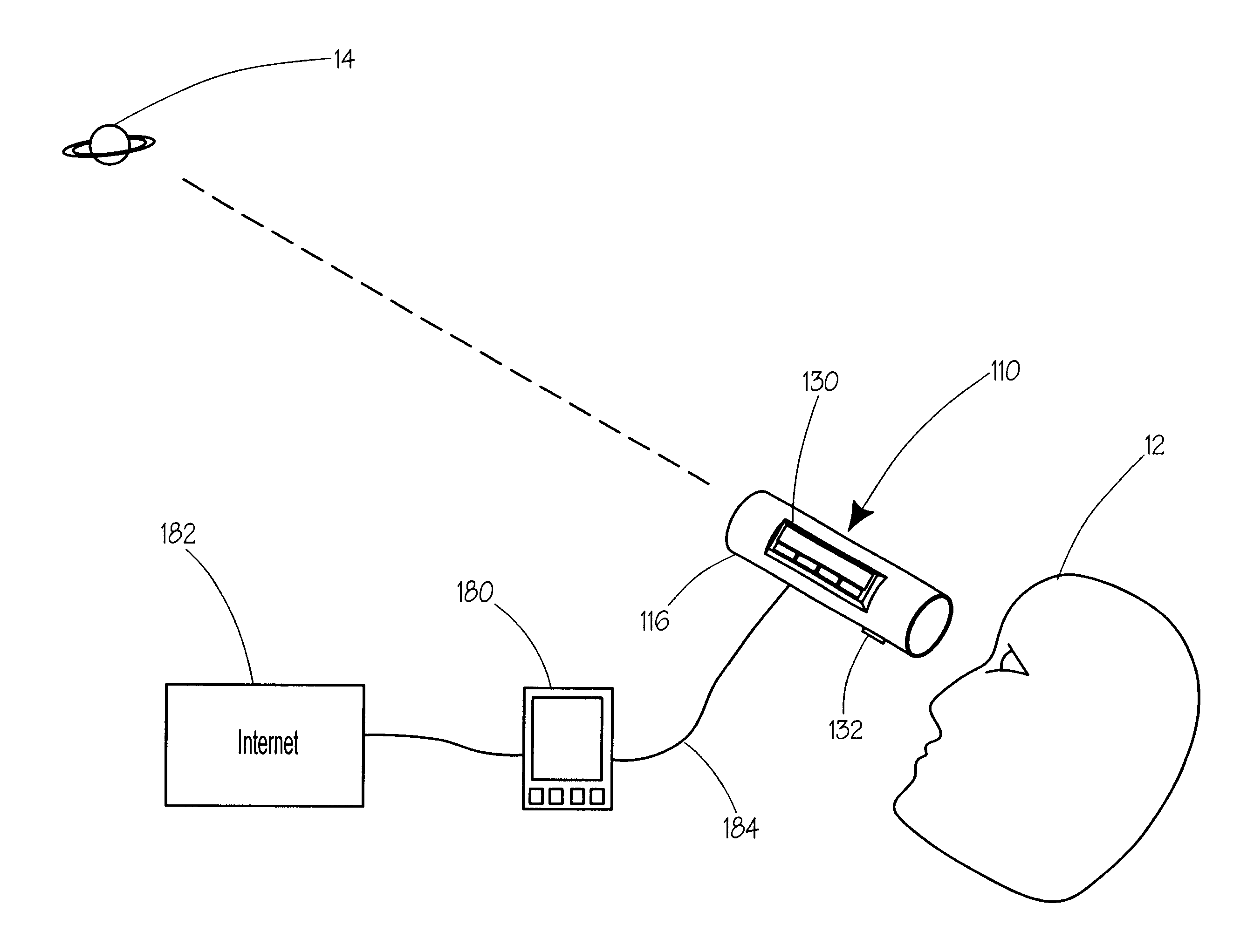
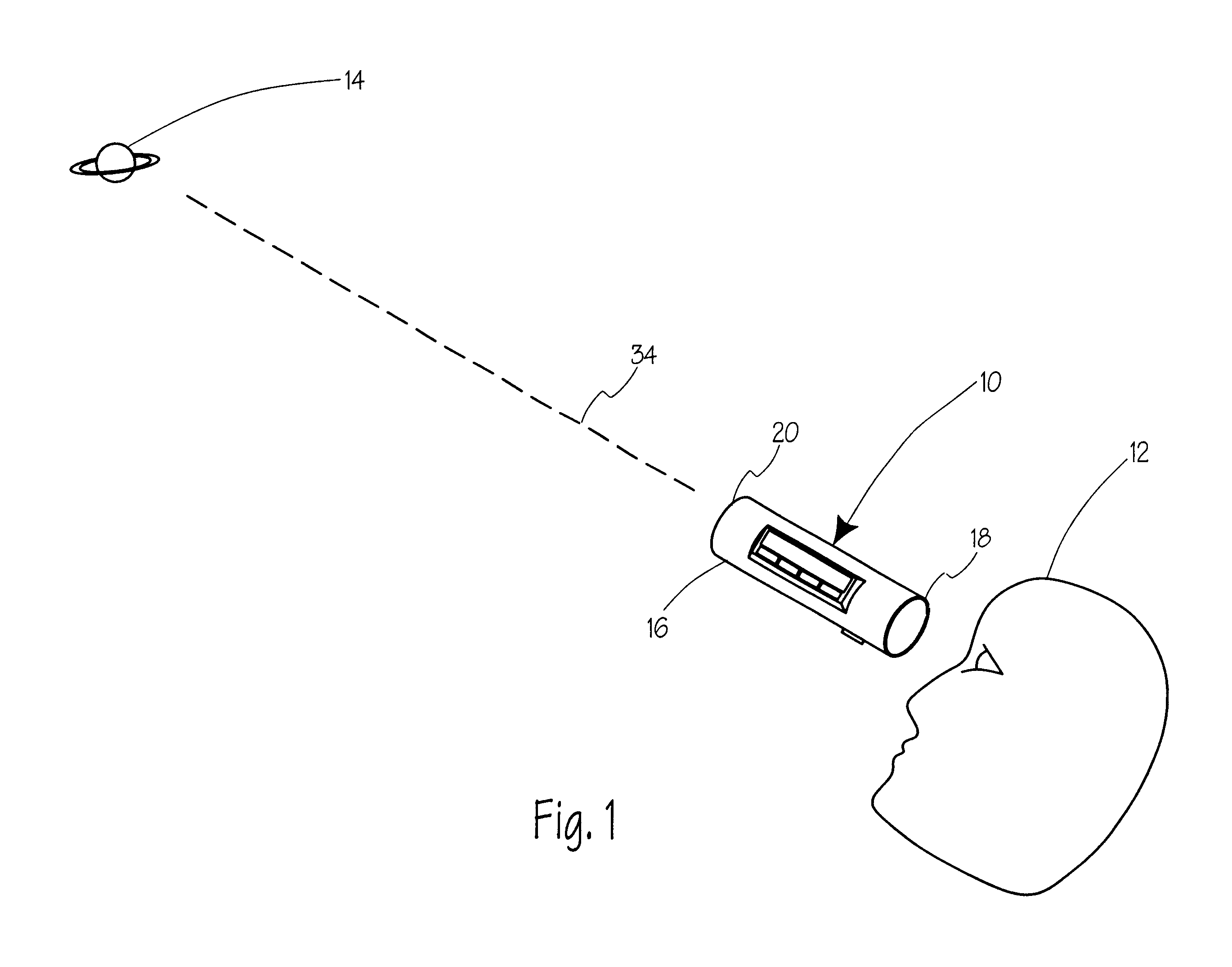
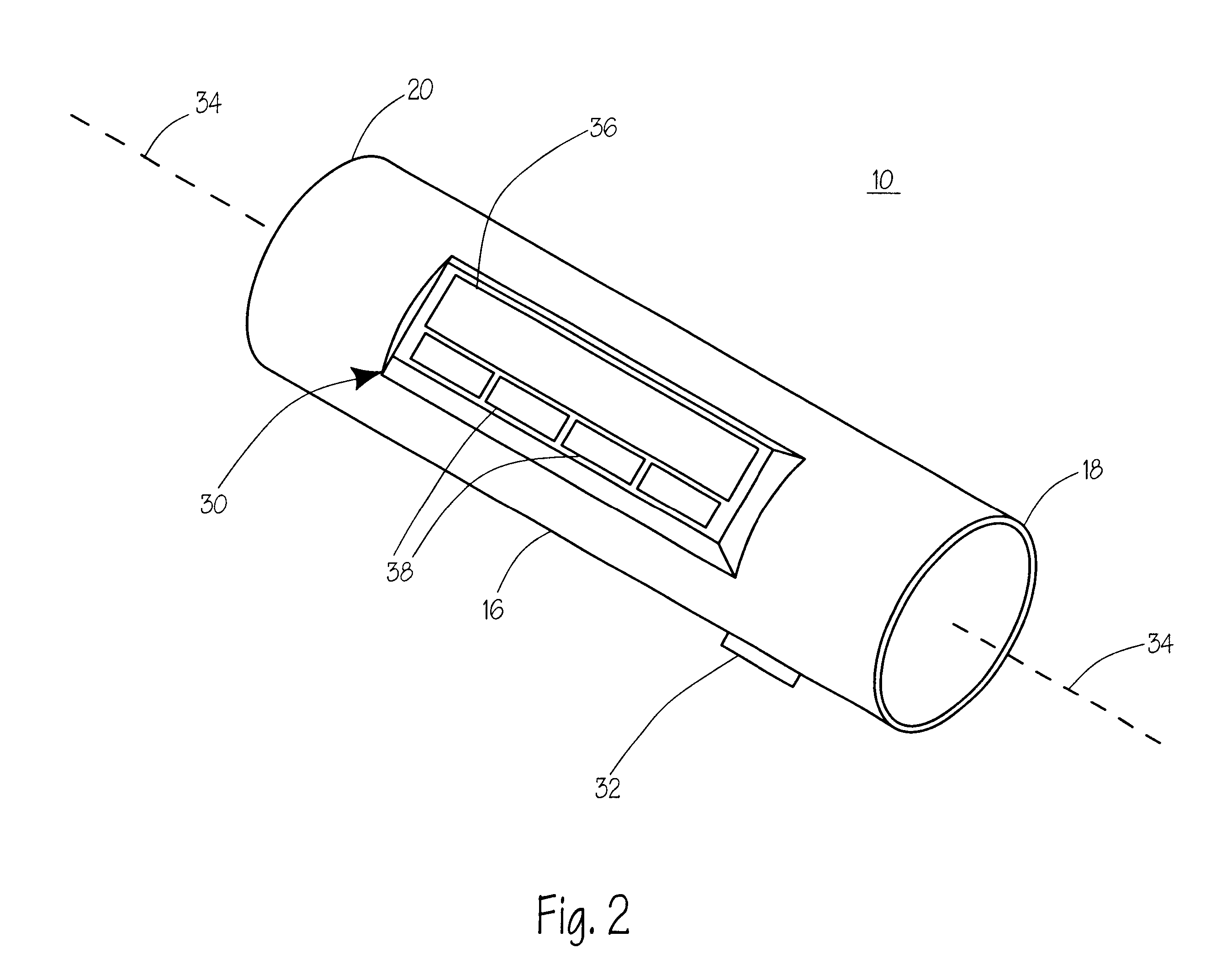
Referring now to the figures, wherein like reference numerals refer to like elements throughout the figures, and specifically to FIG. 1, a celestial object location device (COL device) 10 is being used by a user 12 to locate a celestial object 14. The COL device 10, according to the shown and a preferred embodiment of the invention, has a generally cylindrical housing 16 adapted to be hand-held. Other embodiments of the invention may have housings of other shapes and may or may not be hand-held. Non-limiting examples of such embodiments naturally include telescopes, binoculars, eyepieces, headpieces, and any means for viewing objects. Thus, different embodiments of the object location device can themselves magnify distant objects. In the case of a headpiece, a retinal location sensing device can be used to further determine in what direction the user's eye is pointed. Thus, the user can simply look at an object and the object locator will then identify what the user is looking at.

Th...


PUM


Abstract

A hand-held electronic celestial object-locating device assists in identifying a celestial object or directing a user to a desired celestial object. The device is useful for locating or identifying any celestial object including stars, constellations, planets, comets, asteroids, artificial satellites, and deep sky objects to name a few. The device utilizes sensors for 3-axis magnetic field and 3-axis gravitational field detection. The device utilizes a processor and an electronic database to perform the required calculations. The device's database may be updated through access to the Internet through which the updates may be purchased.

Description

FIELD OF THE INVENTIONSThis invention relates to astronomy, specifically to an electronic device capable of locating and identifying celestial objects.BACKGROUND OF THE INVENTIONSPeople have always been fascinated with the heavens. They have been cited for the origins of the universe and life. Stars and constellations are the basis of fables, myths, and stories in almost every culture on the earth. The stars are used as indicators of peoples' future by some. Sailors and other travelers rely on certain stars and constellations as indicators of position and direction. Further, there is an enormous amount of professional and hobbyist interest in the stars.Both professionals and hobbyists use celestial object identifying devices to locate a star, constellation, planet, comet, asteroid, artificial satellite, deep sky object or other heavenly objects, which shall be referred to collectively as celestial objects. Some existing celestial object identifying devices function by using a combin...

Claims


Application Information

Patent Timeline
Patent Type & Authority Patents(United States)
IPC IPC(8): G09B23/00G09B27/04G09B27/00G09B23/06
CPCG09B23/06G09B27/04G09B27/00
Inventor LEMP, III, MICHAEL
Owner YAMCON
Why Eureka
Try Eureka