Optical reproducing method for optical medium with aligned prepit portion

a technology of optical recording medium and pre-alignment, which is applied in the field of high-density optical recording medium, can solve the problems of increasing tracking error (tracking offset) and difficulty in high-density recording in which the track pitch is narrowed

Inactive Publication Date: 2005-01-18
HITACHI CONSUMER ELECTRONICS CORP
View PDF44 Cites 3 Cited by
  • Summary
  • Abstract
  • Description
  • Claims
  • Application Information

AI Technical Summary

Benefits of technology

(4) In the shift of the disposition of a pit train from one side to the other as described in the above (2), leading edges of pits in the disposition on the other side can be aligned in the radial direction to solve the problems involved in cutting and replica preparation for the same reasons set forth in the (2). In particular, from the standpoint of signal reproduction, a synchronous signal is allotted to pit information immediately after the shift of the pit train so that decision of a channel bit at the specified position may be thought much of, thereby ensuring that the tolerance to the leading edge position can be increased and a possibility that erroneous reading of important data of, for example, address at the position immediately before the shift of a pit train can be decreased.

Problems solved by technology

In the example of JP-A-6-176404, however, the disposition of the prepit area is offset on one side of the center line of the groove or land, so that when an optical spot is caused to track a groove or a land, a tracking error (tracking offset) increases, making it difficult to perform high-density recording in which the track pitch is narrowed.

Method used


Image

  • Optical reproducing method for optical medium with aligned prepit portion
  • Optical reproducing method for optical medium with aligned prepit portion
  • Optical reproducing method for optical medium with aligned prepit portion

Examples


embodiment 1 (

Optical Recording Medium)

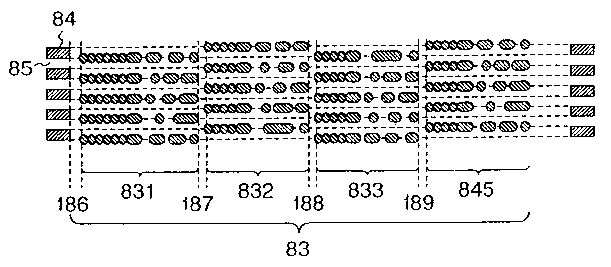
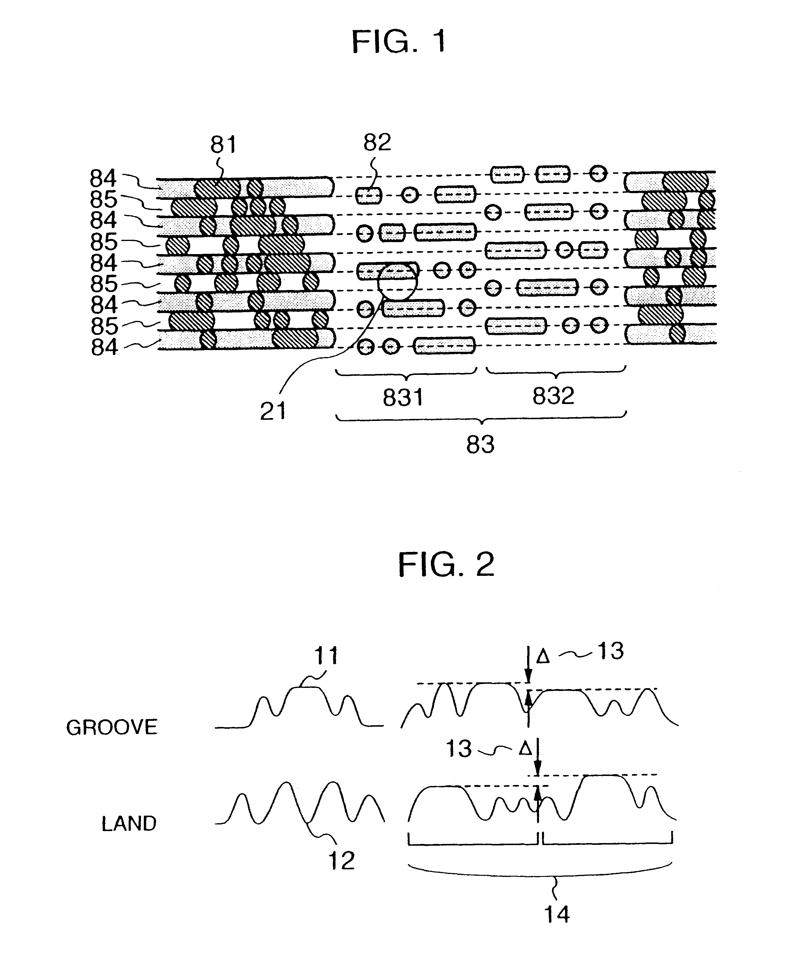
Referring now to FIG. 1, there is illustrated, in enlarged fragmentary plan view form, an optical recording medium of the present invention. Grooves 84 each having a width of 0.6 μm and a depth of 50 nm and lands 85 each having a width of 0.6 μm are arranged alternately in the radial direction of the medium and recorded marks 81 are formed on the two kinds of areas. In other words, each of the groove 84 and land 85 serves as a recording area. In a prepit area 83, any groove is not formed but pits 82 are disposed on an extension of the boundary between a land and a groove. Each of the pits has a width of 0.35 μm and a depth of 50 nm. The prepit area is divided into a first prepit area 831 and a second prepit area 832. In the first prepit region 831, pits 82 are disposed on the upper side, as viewed in the drawing, of the center line of the land 85 and in the second prepit area 832, pits 82 are disposed on the lower side, as viewed in the drawing, of the cente...

embodiment 2

Referring now to FIG. 4, there is illustrated a second embodiment of the present invention. A medium of the present embodiment differs from that of embodiment 1 in that only synchronous information pits 861 to 864 are disposed on the upper side (as viewed in the drawing) of the center line of a groove 841, 842, 843, 844 or 845 and synchronous information pits 861 to 864 and address data pits 871 to 874 are both disposed on the lower side (as viewed in the drawing) of the center line of each of the grooves 84. Preferably, the address data pits 871 to 874 are arranged continuously to the synchronous information pits 861 to 864. For a land 85, the upper and lower side relation is inverted.

Being different from the embodiment 1, the present embodiment has address data arranged on only the upper or lower side of the center line of the groove or the land and therefore the same address data is allotted to the land and groove. In the present embodiment, four divisional prepits areas 831 to 8...

embodiment 3

Referring to FIG. 5, there is illustrated a third embodiment in which identification marks 88 are used to discriminate the land from the groove. In the present embodiment, identification marks 88 for discrimination between the land and the groove are provided independently of the prepit area in the embodiments 1 and 2.

In the present embodiment, a pair of pits (identification marks) 88 are arranged on the upper and lower (as viewed in the drawing) sides of the center line of a groove 841, 843 or 845 but they are not provided for a groove 842 or 844. On the assumption that an optical spot relatively moves from left to right as viewed in the drawing when the medium provided with the above identification marks is reproduced to provide a case of “presence” where the identification marks are seen by the optical spot and a case of “absence” where the identification marks are not seen, “presence, presence” is held for the groove 841, “absence, presence” is held for a land 851, “absence, abs...


PUM

PropertyMeasurementUnit
depthaaaaaaaaaa
depthaaaaaaaaaa
depthaaaaaaaaaa

Abstract

An optical reproducing method using an optical medium having an aligned prepit portion straddled on a plurality of tracks in a radius direction. The prepit portion includes a first and second prepit portion divided in a track direction with a gap therebetween and with a synchronous information prepit of the respective first and second prepit portion being arranged on a boundary of the respective tracks. The synchronous information prepit and the first and second prepit portion is arranged at every two-track pitch in the radius direction and at opposite boundaries of the same track. An optical spot is irradiated on the optical medium, a reflected beam is detected from the optical medium, and information on the optical medium is reproduced by using a signal obtained by the reflected beam.

Description

BACKGROUND OF THE INVENTIONThe present invention relates to an optical recording medium and more particularly to a high-density optical recording medium having a track width smaller than an optical spot diameter.An example of a medium for performing high-density (narrow track) recording is disclosed in, for example, JP-A-6-176404. According to this example, in an optical recording medium having grooves and lands which are formed on a substrate and information recording areas which are formed in association with both the groove and the land, prepits are disposed on a virtual extension line of the boundary between a groove and a land. In particular, the prepits are located on only one side of any specific position of the center line of each groove.With this construction, recording information is formed on both the groove and the land, the prepits have charge of address data representative of the recording areas and one prepit is used in common to a pair of adjacent groove and land to ...

Claims


Application Information

Patent Timeline
Patent Type & Authority Patents(United States)
IPC IPC(8): G11B11/105G11B27/19G11B7/013G11B27/30G11B11/00G11B27/24G11B7/007G11B7/09G11B7/26G11B5/09G11B7/24G11B15/52
CPCG11B7/00718G11B7/00745G11B7/0938G11B7/094G11B7/24085G11B11/10578G11B27/19G11B27/24G11B27/3027G11B7/0901G11B2220/2525G11B2220/20G11B7/26
Inventor MIYAMOTO, HARUKAZUSUKEDA, HIROFUMITERAO, MOTOYASUMINEMURA, HIROYUKIANDOU, TETSUO
Owner HITACHI CONSUMER ELECTRONICS CORP
Why Eureka
Try Eureka