Vertical door conversion kit

a technology for conversion kits and doors, applied in the field of vehicle doors, can solve the problems of distinctly undesirable door swinging out and impacting the object next to the vehicle, affecting the entry and exit of the vehicle, and affecting the door hinges of the conventional type of automobiles

Inactive Publication Date:
View PDF19 Cites 53 Cited by
  • Summary
  • Abstract
  • Description
  • Claims
  • Application Information

AI Technical Summary

Benefits of technology

It is therefore one aspect, advantage, objective and embodiment of the invention to provide a method wherein the bi-directional rotation mechanism prevents the motion of the door in the second vertical plane when the door has not fully completed motion in the first horizontal plane.
It is therefore one aspect, advantage, objective and embodiment of the invention to provide a method wherein the bi-directional rotation mechanism further comprises: at least one sag adjustment device preventing vertical sag of the door during the first horizontal plane of motion.

Problems solved by technology

Conventional door hinges on automobiles have a number of problems.
Since vehicles quite often end up parked next to either another vehicle or an abrasive concrete surface, allowing the door to swing out and impact the object next to the vehicle is distinctly undesirable.
The result is that around one half of the available arc beside the vehicle is covered by the door, making entry and egress a bit more difficult.
Occasionally, a user may be blocked from even reaching the vehicle's entryway by the body of the door, for example, when the door is already open and the user approaches the vehicle from the front.
Given the omnipresence of traffic, such diversions from simple entry are dangerous to users, and when a vehicle is parallel parked, a projecting door on the driver's side of the vehicle becomes an obstacle and danger to traffic.
The projecting door itself is also in danger of being struck and damaged by passing traffic.
Certain expensive types of automobiles have frames custom designed to support vertically hinged doors.
The hinge is located at the top of the door, not the front, and the form of rotation would necessarily involve a large and undesirable swing outwards away from the vehicle body, making opening the door impossible when parked close to another vehicle or other obstruction.

Method used


Image

  • Vertical door conversion kit
  • Vertical door conversion kit
  • Vertical door conversion kit

Examples


Embodiment Construction

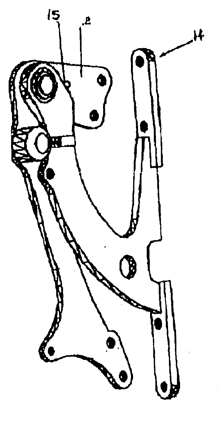
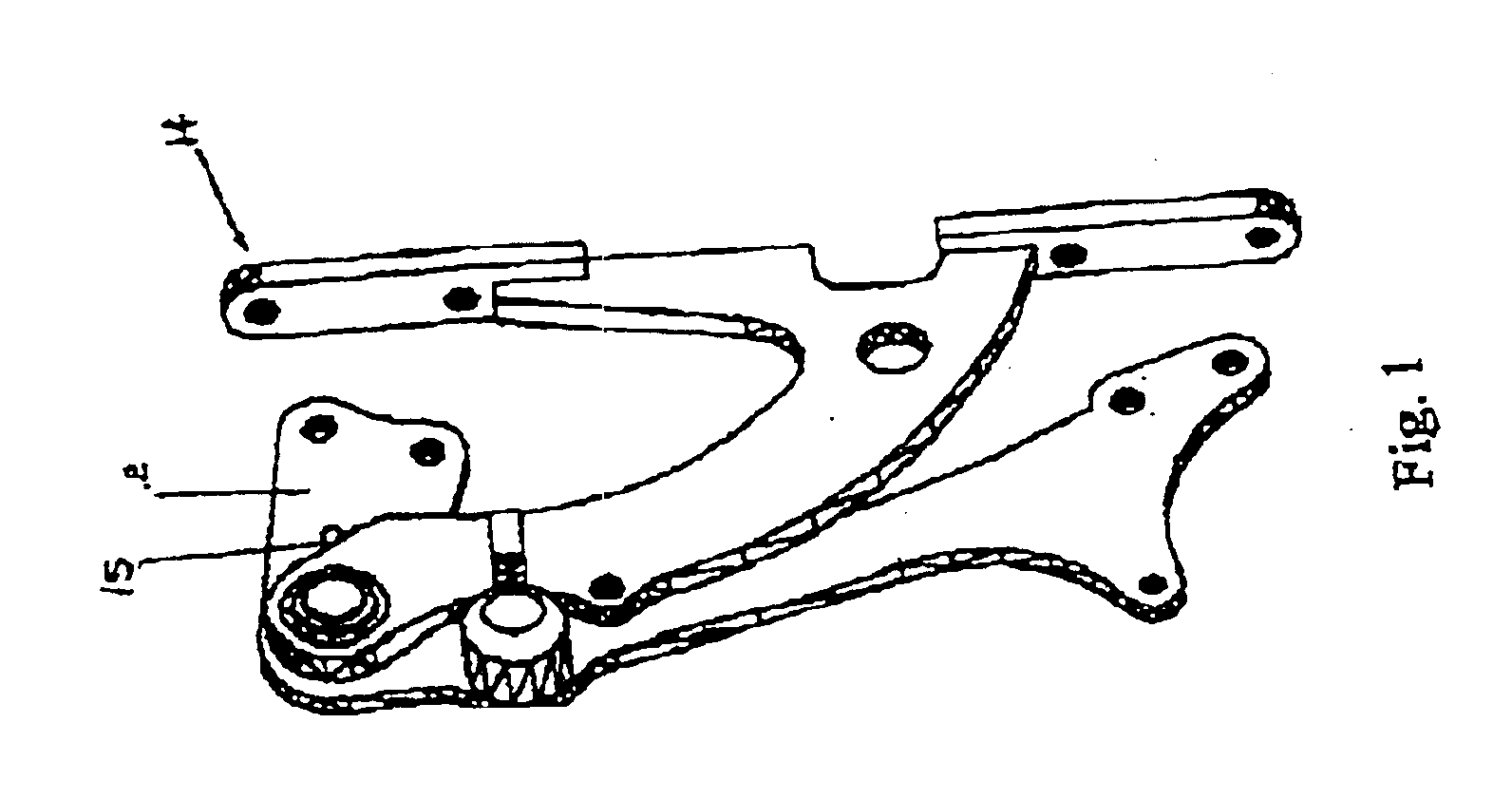
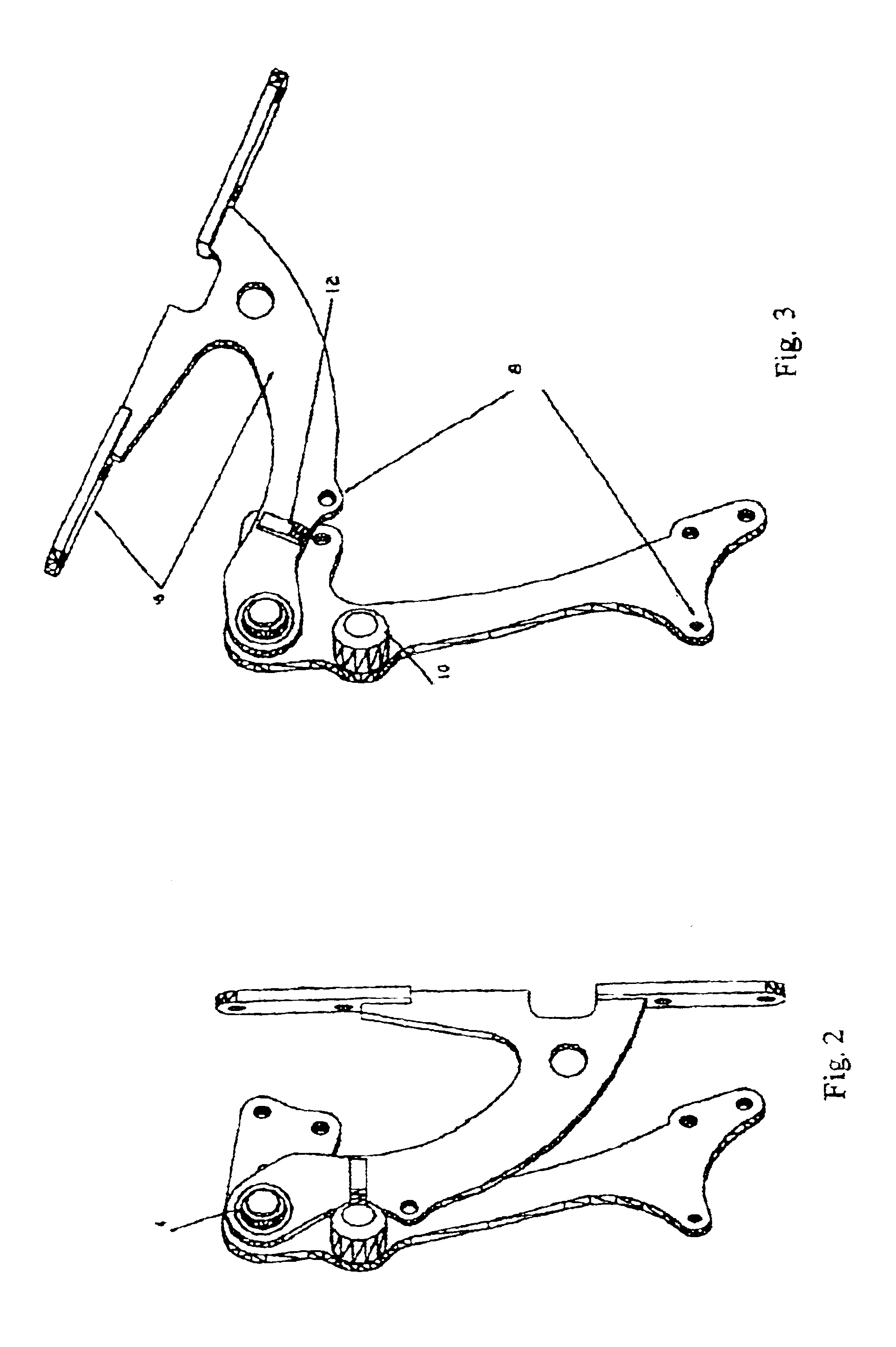
The present invention teaches several bi-directional rotation mechanisms: various types of hinges which allow rotation in more than one plane of motion. In general, the following embodiments of the bi-directional rotation mechanism have at least three distinctive positions: a first position corresponding to the door being closed, a second position corresponding to the door having opened through the horizontal plane, and a third position corresponding to the door having opened upwards from the second position through the vertical plane. One feature of the present invention is the ability in embodiments to allow substantially horizontal motion in a first horizontal arc or plane, followed by substantially vertical motion in a second vertical plane or arc, for opening the door. For closing, this sequence is reversed. The substantially horizontal motion is motion which allows the vehicle door to clear the vehicle frame, even on vehicles having frames NOT specifically designed for vertica...


PUM


Abstract

A vehicular door hinge mechanism provides for a motion in two different directions at two different portions of the door's motion cycle. The present invention provides a hinge which allows the door of the vehicle to move outwards in a substantially horizontal plane for a predetermined arc, then move vertically upwards on another predetermined arc thereafter. The invention comprises a hinge mechanism having a chassis mounting plate and a swingarm. Between them is either a pivotal bearing or a hinge designed to allow the staged two dimensional motion of the invention. A spring or cylinder is connected at its ends to the chassis mounting plate and the swingarm. A horizontal pressure bearing surface and a cam adjuster cooperate to provide strength and precise fit of the door with the vehicle.

Description

FIELD OF THE INVENTIONThis invention relates generally to vehicle doors and specifically to door hinge mechanisms allowing vehicle doors to rotate upward from the vehicle when opened.BACKGROUND OF THE INVENTIONConventional door hinges on automobiles have a number of problems. As is well known, such conventional systems hinge the door at the front of the edge and swing the door outwards through a horizontal arc which brings the rear edge of the door quite distant from the vehicle body. A spring action which assists in the opening of the door attempts to push the door open to substantially the full distance it is capable of opening. Opening the door in this fashion results in either the door's rear edge hitting whatever the vehicle is stopped next to or else requires the user to “fight” the door continuously as they get out of the vehicle, to prevent the door from reaching the full extension outwards. Since vehicles quite often end up parked next to either another vehicle or an abrasi...

Claims


Application Information

Patent Timeline
Patent Type & Authority Patents(United States)
IPC IPC(8): E05D3/00E05D3/06E05D3/10E05D15/56
CPCB60J5/0472E05D3/10E05D3/127E05D15/00E05D5/062E05Y2900/531Y10T16/53257Y10T16/52Y10T16/551Y10T16/5472Y10T16/5327Y10T16/5323
Inventor HAM, DEMETRIUS CALVIN
Why Eureka
Try Eureka