Clutch mechanism for electronic locks

a technology of electronic locks and latches, applied in the direction of mechanical control devices, keyhole guards, instruments, etc., can solve the problems of less secure than those based on latches, less secure than those based on clutches, and very high stress, so as to achieve greater safety, better aesthetics, and greater security

Inactive Publication Date: 2005-01-25
SALTO SYST SL
View PDF10 Cites 67 Cited by
  • Summary
  • Abstract
  • Description
  • Claims
  • Application Information

AI Technical Summary

Benefits of technology

The placement inside the inner escutcheon provides the advantages of greater security and better aesthetics:
Greater security since it is protected against manipulation from the outside and against adverse climatic conditions; and better aesthetics since the outer escutcheon does not need any extraordinary dimensions for housing the clutch mechanisms.

Problems solved by technology

Solutions based on a latch, though they are simpler, are less secure than those based on a clutch since the latch has to resist all kinds of stresses that are applied to the handle when an attempt is made to force it, while the clutch simply does not transmit those stresses to the lock.
The problems that appear are due to the necessarily small diameter of the shafts so that they can be compatible with standard locks.
The first problem is a consequence of the stresses borne by the mechanism.
As this radius is very small, the stress is very great and wear takes place very quickly.
The second problem is also caused by the small diameter of the first shaft, which involves that it cannot have more than two slots in order to keep its strength within acceptable minima, since each slot reduces its cross-section.
It may therefore be necessary to turn the outer handle under no load up to 180°, which produces an uncomfortable sensation for the user.

Method used


Image

  • Clutch mechanism for electronic locks
  • Clutch mechanism for electronic locks
  • Clutch mechanism for electronic locks

Examples


Embodiment Construction

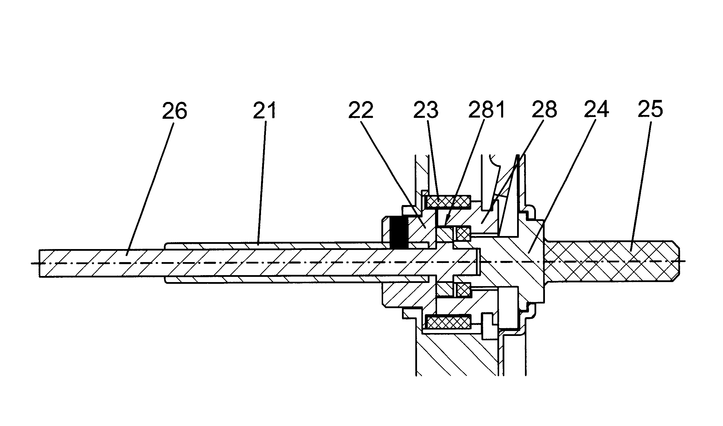
In general terms, the clutch mechanism for electronic locks, constituting the object of the invention, solves both problems referred to above and maintaining the advantages of being located inside the inner escutcheon and of being able to be adapted to any lock since the actuation shafts have standard dimensions.

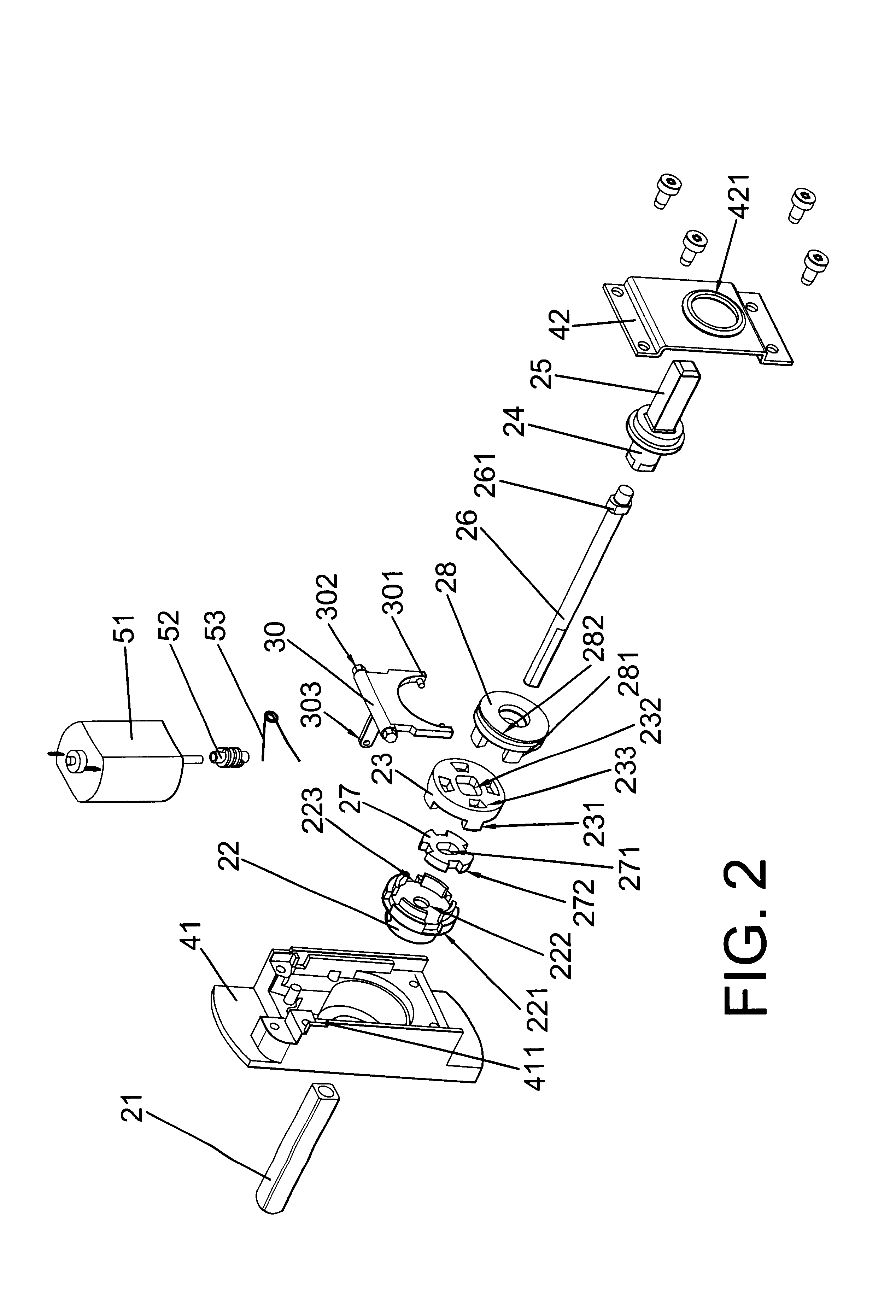
By means of a totally different configuration of the clutch, the advantage is achieved that the stresses suffered by the interacting parts are the least possible and that the rotation of the outer handle under no load is minimised. Furthermore it permits a very simple assembly.

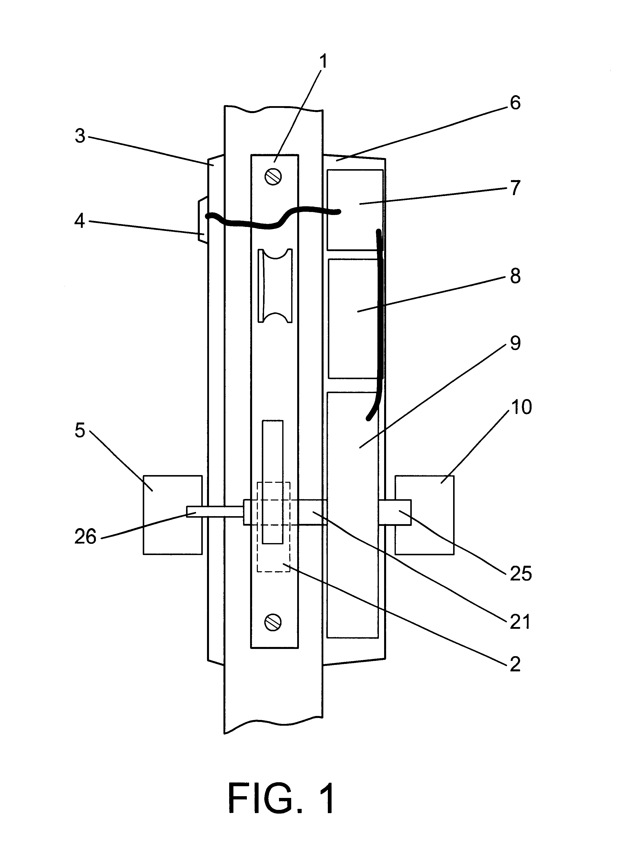
The electronic lock includes an outer escutcheon that holds the key reader and an outer control knob for operating the lock systems. The inner escutcheon contains the electronic control circuit powered by batteries, the clutch mechanism and an inner operating knob.

The clutch mechanism has two concentric shafts, one of which acts on the tumbler, while the other freely rotates with respect to the first w...


PUM


Abstract

This mechanism is intended for being located in the inner escutcheon of the lock and its purpose is to minimize the forces transmitted, thereby preventing premature wear, as well as being able to be adaptable to any lock. Its structure permits to minimize the turning of the handle or outer operating knob under no load.
The outer escutcheon (3) holds the key reader (4) and an outer knob (5) while the inner escutcheon (6) contains the electronic control circuit (7) powered by batteries (8), the clutch mechanism (9) and an inner operating knob (10). Exiting from the clutch mechanism (9) are two concentric shafts (21, 26), one of which acts on the tumbler (2) of the lock and the other (26) which rotates freely in its interior and to which the outer knob (5) is connected.
A validated key activates an electric motor (51) or similar which displaces a collar (28) causing the clutch element (27) to bring both concentric shafts (21, 26) together temporarily, forming a single unit and permitting the opening of the lock.

Description

OBJECT OF THE INVENTIONThis invention, according to the statement of this description, comprises a clutch mechanism for electronic locks, which involves notable relevant and advantageous characteristics compared to those currently used for the same purpose.It is an object of the invention to incorporate the clutch mechanism inside the inner escutcheon of a lock and thereby permit to be used with a wide range of mortise locks, even with locks that are already installed.The placement inside the inner escutcheon provides the advantages of greater security and better aesthetics:Greater security since it is protected against manipulation from the outside and against adverse climatic conditions; and better aesthetics since the outer escutcheon does not need any extraordinary dimensions for housing the clutch mechanisms.BACKGROUND OF THE INVENTIONElectronic locks are characterised in that they have a mechanical lock that physically secures the door to the frame and having certain electroni...

Claims


Application Information

Patent Timeline
Patent Type & Authority Patents(United States)
IPC IPC(8): E05B47/06
CPCE05B47/068E05B2047/0031Y10T70/5416Y10T70/5823Y10T70/7062E05B47/0676
Inventor IMEDIO OCANA, JUAN ANTONIO
Owner SALTO SYST SL
Why Eureka
Try Eureka