Smoothly shifting multispeed transmission

a transmission and multi-speed technology, applied in mechanical equipment, transportation and packaging, gear shifting, etc., can solve the problems of increasing the number and severity of difficult shifts, jerky shifts, and complex simultaneous shifts between adjacent gear ratios, so as to and reduce the difficulty of shifting

Active Publication Date: 2005-01-25
BLUE LEAF I P +1
View PDF9 Cites 23 Cited by
  • Summary
  • Abstract
  • Description
  • Claims
  • Application Information

AI Technical Summary

Benefits of technology

The invention produces a nearly geometric progression of the ratios, but, because of the required double clutch swaps for some of the shifts, with a slight compromise of shift quality. For the present invention, the most difficult downshifts involve shifting the 3 speed section up from 1st to 3rd while downshifting the 11 speed section. However, due to the small ratio steps, this only involves about a 1.28 to 1 speed increase from the input section. This is a great improvement over all current and

Problems solved by technology

However, in such transmissions some of the shifts between adjacent gear ratios require complex simultaneous changeovers in two or three of the transmissions.
These complex changeovers frequently result in jerky shifts.
Moreover, the tendency to increase the spread of the overall ratio over the years has increased the number and severity of these difficult shifts.
However, such a transmission causes discontinuities in the vehicle motion, the so called jerky shifts, when one or more sections are being upshifted while another is

Method used


Image

  • Smoothly shifting multispeed transmission
  • Smoothly shifting multispeed transmission
  • Smoothly shifting multispeed transmission

Examples


Embodiment Construction

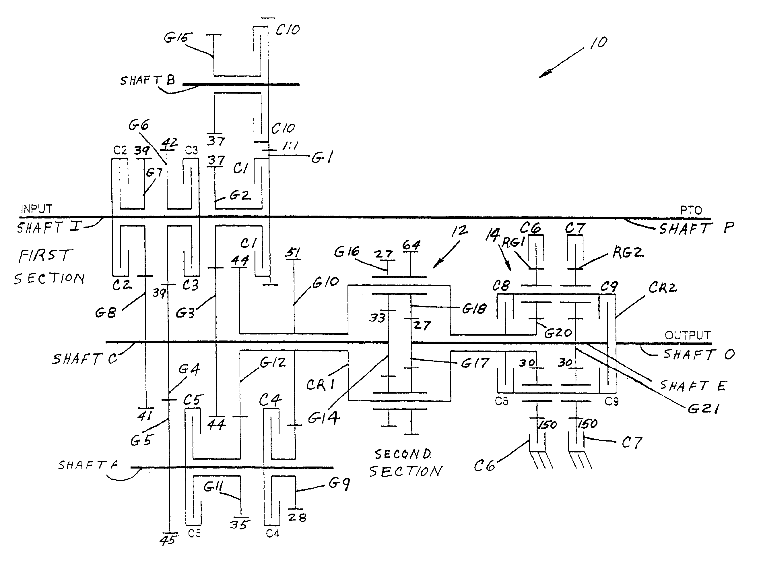
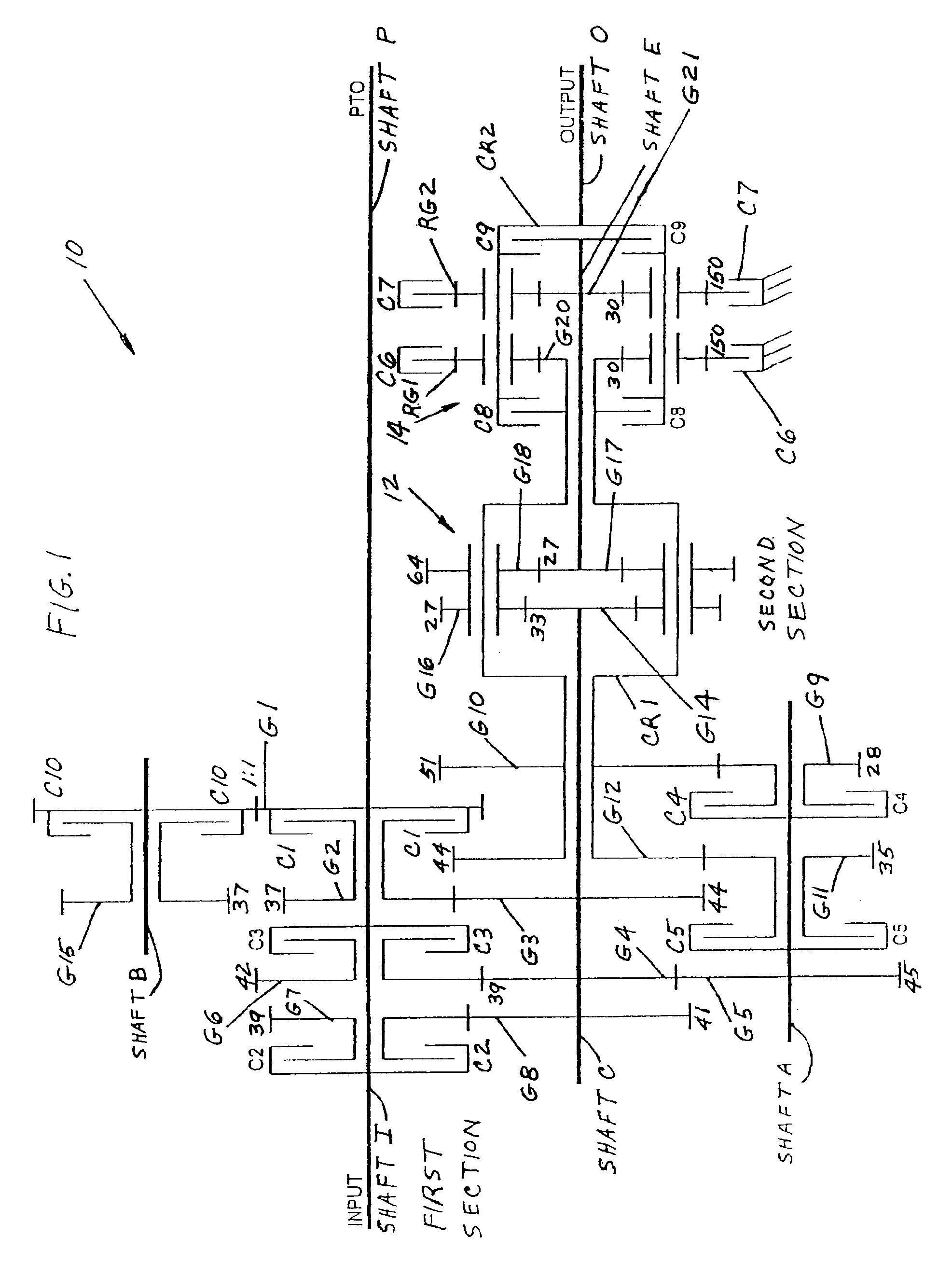
FIG. 1 is a schematic diagram of transmission 10 of the preferred embodiment of the invention in which each of the ten clutches is identified by the designation C1 through C10 located adjacent to the symbol for the clutch, shafts are identified adjacent to their symbols, and gears are identified by numerals preceded by the letter G and identifying lines. It should also be understood that the clutches are all pictured in a vertical orientation and labeled near both ends for clarity. On the other hand, although all gears are also pictured in a vertical orientation and have two ends, they are typically labeled only once. The number of teeth in each gear of the preferred embodiment is indicated by the number adjacent to the symbol representing the gear in FIG. 1. Furthermore, the relative size relationship of gear diameters is also shown in FIG. 1. That is, larger gears are shown larger and smaller gears are shown relatively smaller. Moreover, where possible, driver and driven gears are...


PUM


Abstract

The apparatus is a 28 speed, two section, transmission that requires only a single clutch swap for most changeovers between adjacent ratios. It uses a first section with three close ratio forward speeds and one reverse along with a second section that is an 11 speed, wide ratio, transmission. The two transmission sections are arranged in series resulting at least 28 usable forward speeds. The second section includes an intermediate planetary gear set without a ring gear and an output planetary gear set that is a conventional simple planetary gear set with a two sun gears, two planes of planetary gears on a single carrier, and two ring gears.

Description

BACKGROUND OF THE INVENTIONThis invention deals generally with mechanical transmissions and more specifically with a power shift transmission with a large number of forward ratios and very smooth shifts between gear ratios.Power shift transmissions have been in use for agricultural tractors for about 40 years. Such transmissions now provide the capability of shifting through all the forward gears while moving and while under load without using a clutch pedal. The only action required by an operator is the selection of the desired gear. The actual changeover, including the operation of one or more clutches is electronically controlled and performed by hydraulically powered clutches.In order to provide a wide range of ratios divided into a large number of small forward ratio steps in a transmission of practical size and reasonable cost, such transmissions are actually built as two or three transmissions in a series arrangement. Such a transmission is disclosed in U.S. Pat. No. 5,036,7...

Claims


Application Information

Patent Timeline
IPC IPC(8): F16H37/02F16H37/04
CPCF16H3/66F16H2003/0818F16H2200/003Y10T74/19233F16H2200/0065
Inventor BULGRIEN, GARTH H.
Owner BLUE LEAF I P
Why Eureka
Try Eureka