
Pressurized valve seal

a pressurized valve and sealing technology, applied in the field of valve seals, can solve the problems of compromising the the sealing engagement of the valve sealing member to the seating material is ineffective in sealing the port or aperture, and the valve sealing of the seating member to the sealing gland continues to experience problems with maintaining sealing, so as to facilitate the application of fluid pressur

Inactive Publication Date: 2005-01-25
WESTPORT FUEL SYST CANADA INC
View PDF41 Cites 16 Cited by
  • Summary
  • Abstract
  • Description
  • Claims
  • Application Information

AI Technical Summary

Benefits of technology

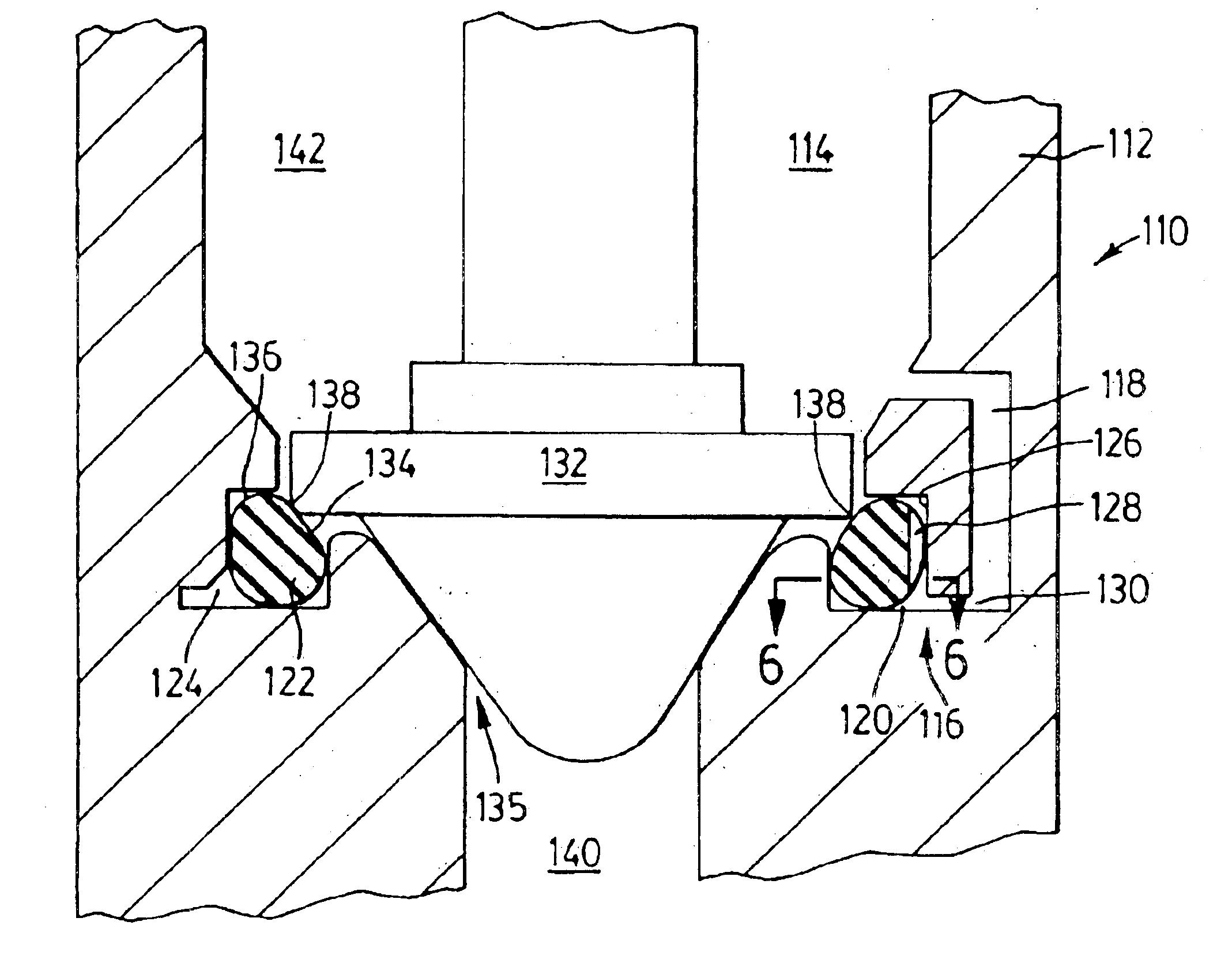
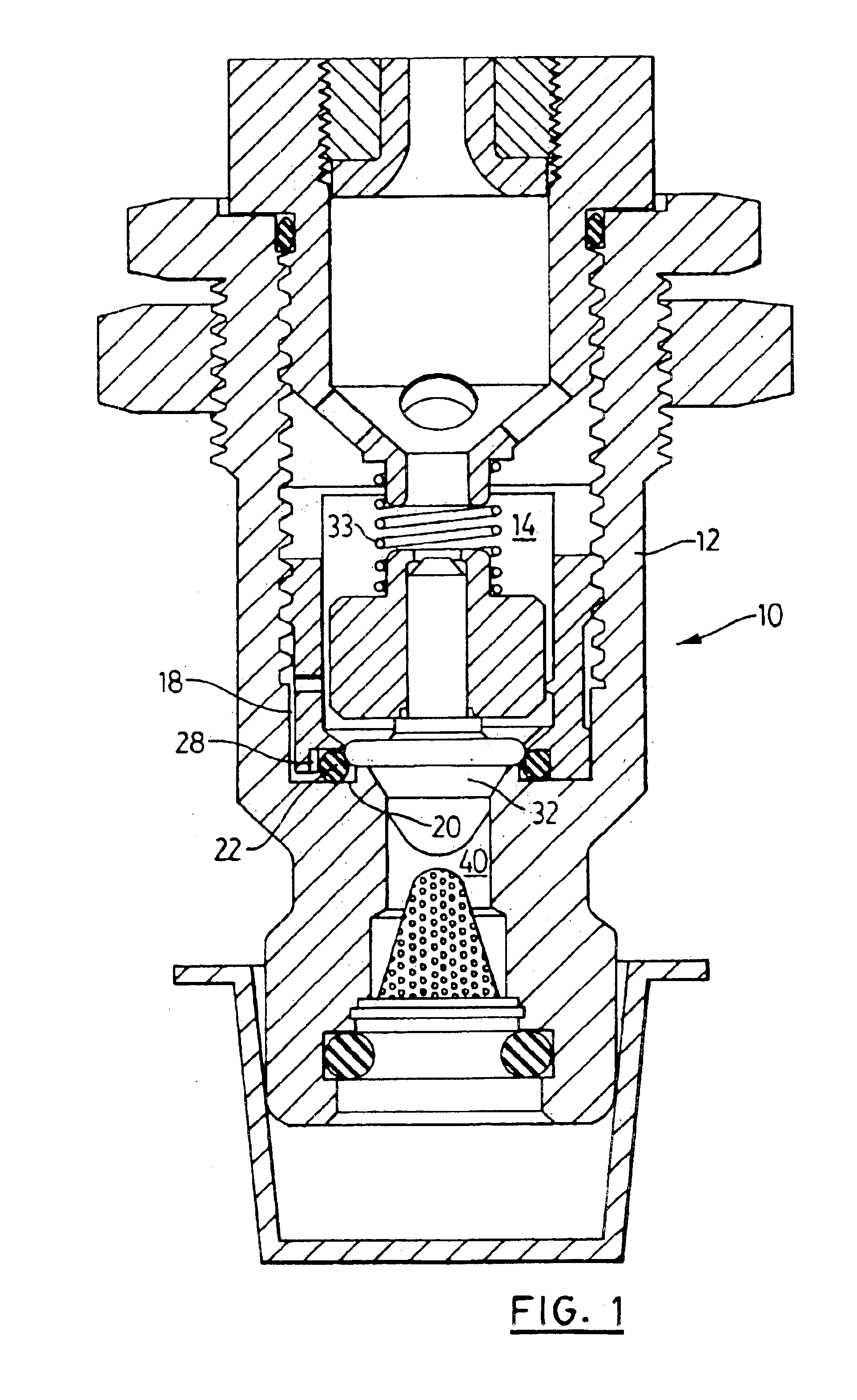
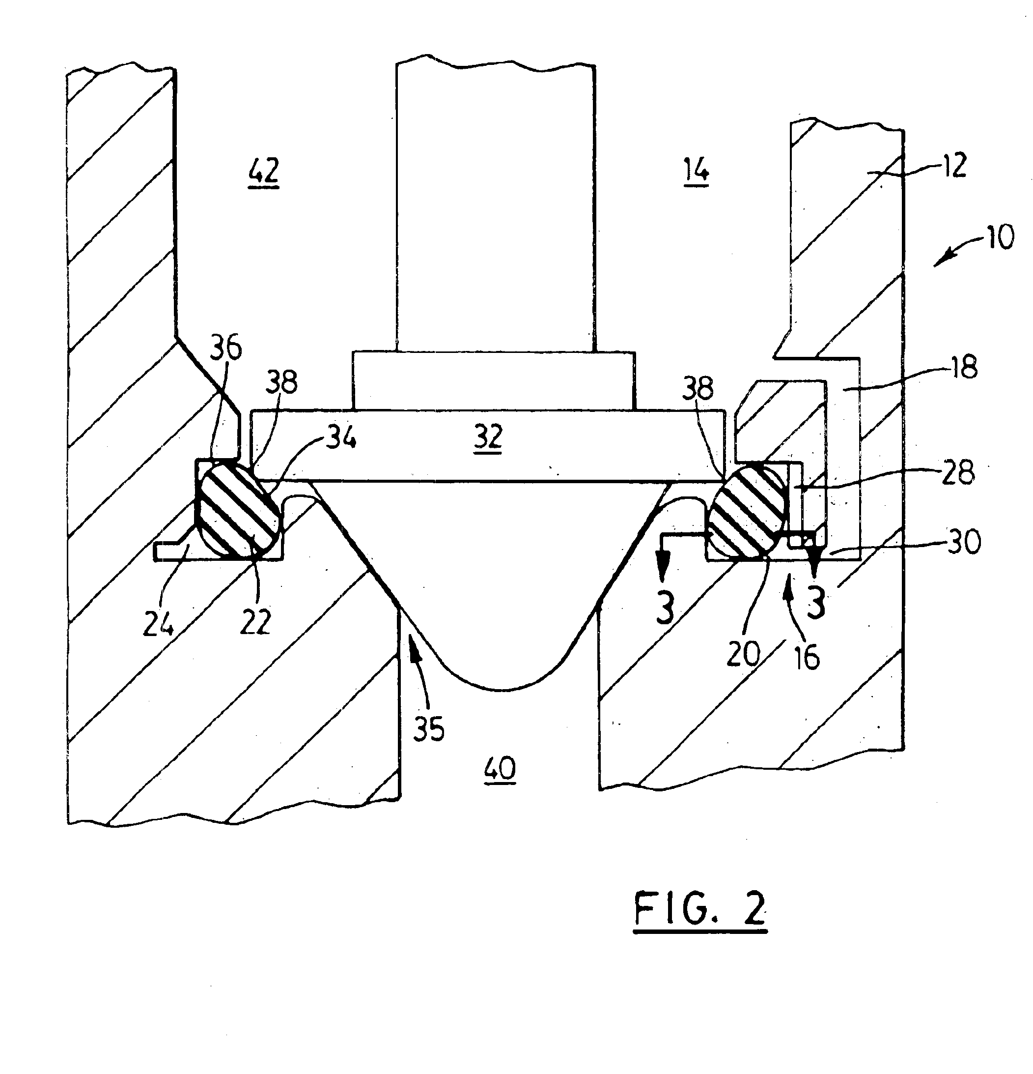
In its broad aspect, the invention provides a valve for controlling a fluid which exerts a fluid pressure. The valve includes a body, which has a fluid passage and a valve seat defining an orifice. The valve seat includes a sealing gland having a support surface, and the support surface includes a notch. The valve seat also includes a resilient valve seat member disposed within the sealing gland. In addition, the body includes a valve sealing member disposed within the fluid passage and configured to seat against the valve seat member to effect sealing of the valve sealing member to the valve seat and thereby to close the orifice. The notch is configured to facilitate the application of the fluid pressure on the valve seat member to prevent leakage through the orifice and between the valve sealing member and the sealing gland when the valve sealing member is seated against the valve seat member. The valve seat member includes a first pressure responsive surface exposed to the fluid passage, and including a valve engaging surface portion. The valve engaging surface portion is configured to engage the valve sealing member to effect sealing of the valve sealing member to the valve seat. The valve seat member also includes a second pressure responsive surface configured to receive the application of the fluid pressure. The notch is positioned to face the second pressure responsive surface. Also, the notch is configured to facilitate the application of the fluid pressure on the second pressure responsive surface to counterbalance applications of forces on the first pressure responsive surface.
In yet another aspect, the invention provides a valve for controlling a fluid exerting a fluid pressure. The valve includes a body having a fluid passage and a valve seat defining an orifice. The valve seat includes a sealing gland including a cavity, and a resilient valve seat member disposed within the sealing gland. The body also includes a valve sealing member disposed within the fluid passage and configured to seat against the valve seat member to effect sealing of the valve sealing member to the valve seat and thereby to close the orifice. The sealing gland includes two or more spaced apart apertures configured to distribute fluid pressure within the cavity to act upon the valve seat member to prevent leakage through the orifice when the valve sealing member is seated against the valve seat member. The spaced apart apertures are configured to facilitate the application of the distributed fluid pressure on the valve seat member to prevent leakage through the orifice and between the valve sealing member and the sealing gland when the valve sealing member is seated against the valve seat member.

Problems solved by technology

Under these circumstances, sealing engagement of the valve sealing member to the seating material is ineffective in sealing the port or aperture.
Valves with pressurized seals continue to experience problems with maintaining sealing engagement of the seating surface against the sealing gland.
As a result, fluid pressure introduced into the sealing gland cavity is not necessarily effective in opposing the fluid pressure forces acting on the seating member from within the fluid passage, thereby potentially compromising the sealing of the seating member to the sealing gland.

Method used


Image

  • Pressurized valve seal
  • Pressurized valve seal
  • Pressurized valve seal

Examples


Embodiment Construction

Referring to FIGS. 1, 3, in one embodiment, the present invention provides a valve 10 comprising a body 12 including a fluid passage 14, a valve seat 16, and a communication channel 18. The valve seat 16 includes a sealing gland 20 and a resilient valve seat member 22 disposed and supported within a cavity 24 of the sealing gland 20. The sealing gland 20 has a support surface 26 including a notch 28. The notch 28 defines a channel which forms part of the cavity 24. The communication channel 18 effects communication between the fluid passage 14 and the cavity 24, and, therefore, the notch 28, through an aperture 30 provided in the sealing gland 20. In this respect, the communication channel 18 provides a means for effecting communication between the cavity 24 and a source of fluid pressure (in this case, the fluid passage).

The body 12 is made of a material which is significantly harder than the material of construction of the valve seat member 22. The valve seat member 22 is made of ...


PUM


Abstract

A valve for controlling flow of a fluid exerting a fluid pressure. The valve has a body including a fluid passage for the fluid, and a valve seat positioned adjacent to the fluid passage at an orifice coaxial with the fluid passage. The valve seat includes a sealing gland defining a cavity therein, and the sealing gland has a support surface adjacent to the cavity and a resilient valve seat member within the cavity. The valve seat member includes a first pressure responsive surface adjacent to the orifice and a second pressure responsive surface substantially opposed to the first pressure responsive surface. The support surface includes a notch for positioning a portion of the support surface a distance apart from the second pressure responsive surface.

Description

FIELD OF INVENTIONThis invention relates to valve seals, and particularly pressurized valve seals.BACKGROUND OF THE INVENTIONValves typically employ a resilient seating material, such as an o-ring, about the perimeter of a port or aperture. The resilient seating material is intended to engage and be compressed by a movable valve sealing member to effect sealing of the port or aperture. The seating material is disposed and contained within a sealing gland, provided in the body of the valve. In order to achieve desirable sealing properties, the seating material must be sealingly engaged to the sealing gland both upstream and downstream of the point of sealing engagement between the valve sealing member and the seating material. Under some operating conditions, the seating member moves away from the sealing gland, creating a flow path, allowing fluid to leak through the port or aperture even though the valve sealing member is sealingly engaged to the seating material. Under these circu...

Claims


Application Information

Patent Timeline
Patent Type & Authority Patents(United States)
IPC IPC(8): F16J15/48F16K1/44F16K1/46F16J15/46F16K1/32
CPCF16J15/48F16K1/465F16K1/443
Inventor LANTING, HENRY A.WOO, PO P.
Owner WESTPORT FUEL SYST CANADA INC
Learn More