Method of holding a part in position in an assembly station

a technology of assembly station and part, which is applied in the direction of metal-working holders, soldering auxiliaries, supporters, etc., can solve the problems of large flexibility limit of assembly station, inconvenience of assembly station staff, so as to simplify the tooling of assembly station. , the effect of flexible us

Inactive Publication Date: 2005-01-25
ABB BODY & WHITE
View PDF13 Cites 6 Cited by
  • Summary
  • Abstract
  • Description
  • Claims
  • Application Information

AI Technical Summary

Benefits of technology

The present invention seeks to provide a solution for use in assembling parts (at least two parts) and in particular automotive bodywork parts, which takes advantage of the accuracy of robots

Problems solved by technology

That conventional disposition suffers from the major drawback of requiring the assembly station to implement tools that are dedicated to each of the parts received.
That requirement constitutes a major limit on assembly station flexibility, i.e. on its capacity to receive different types of part.
The assembly station then becomes very cluttered by means for handling these sets of tools (which are often presented in the form of prefitted pallets.
It is also necessary for the handling means to be manufactured with care so that the sets of tools are put into place as accurately as possible within the station and

Method used


Image

  • Method of holding a part in position in an assembly station
  • Method of holding a part in position in an assembly station
  • Method of holding a part in position in an assembly station

Examples


Embodiment Construction

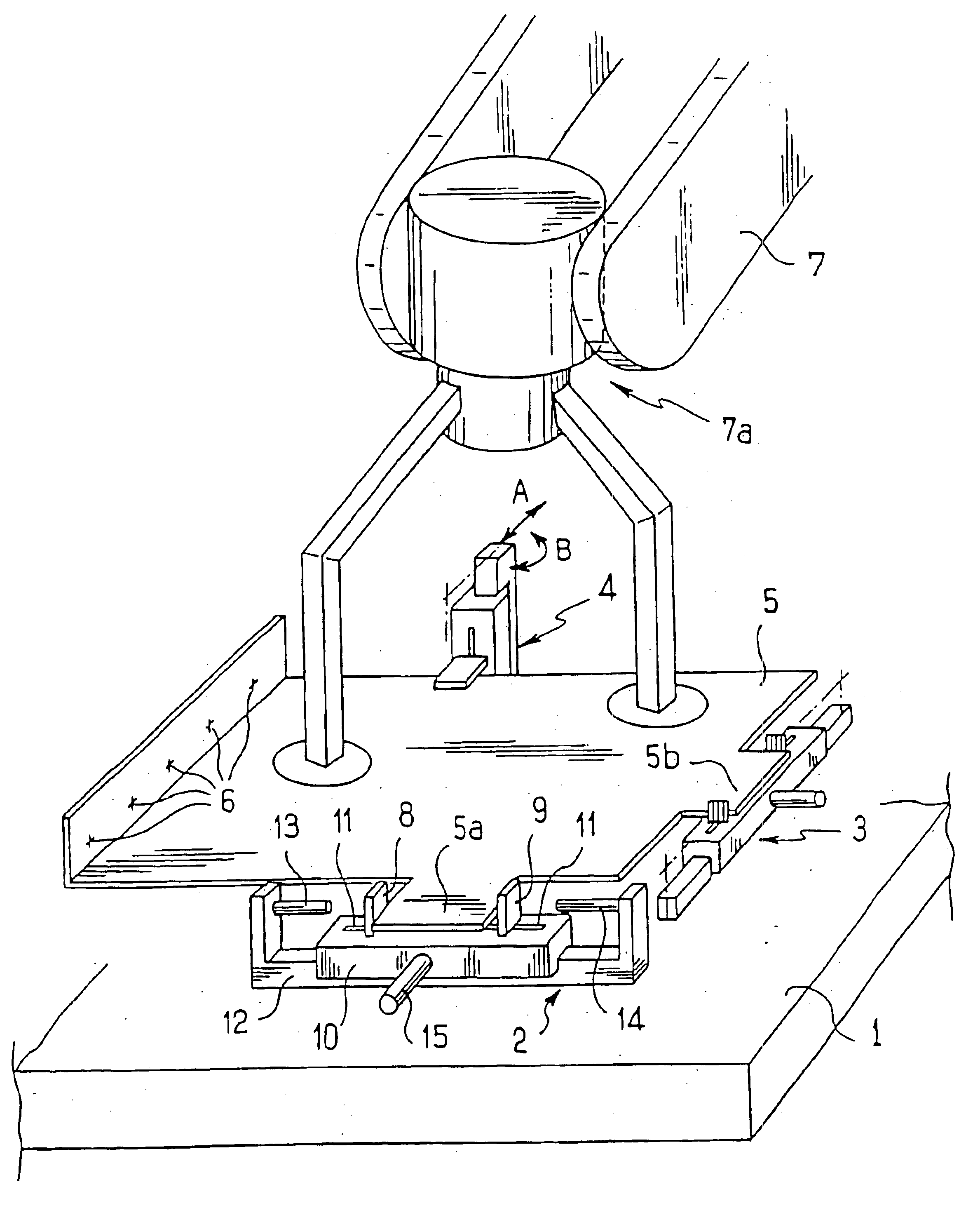
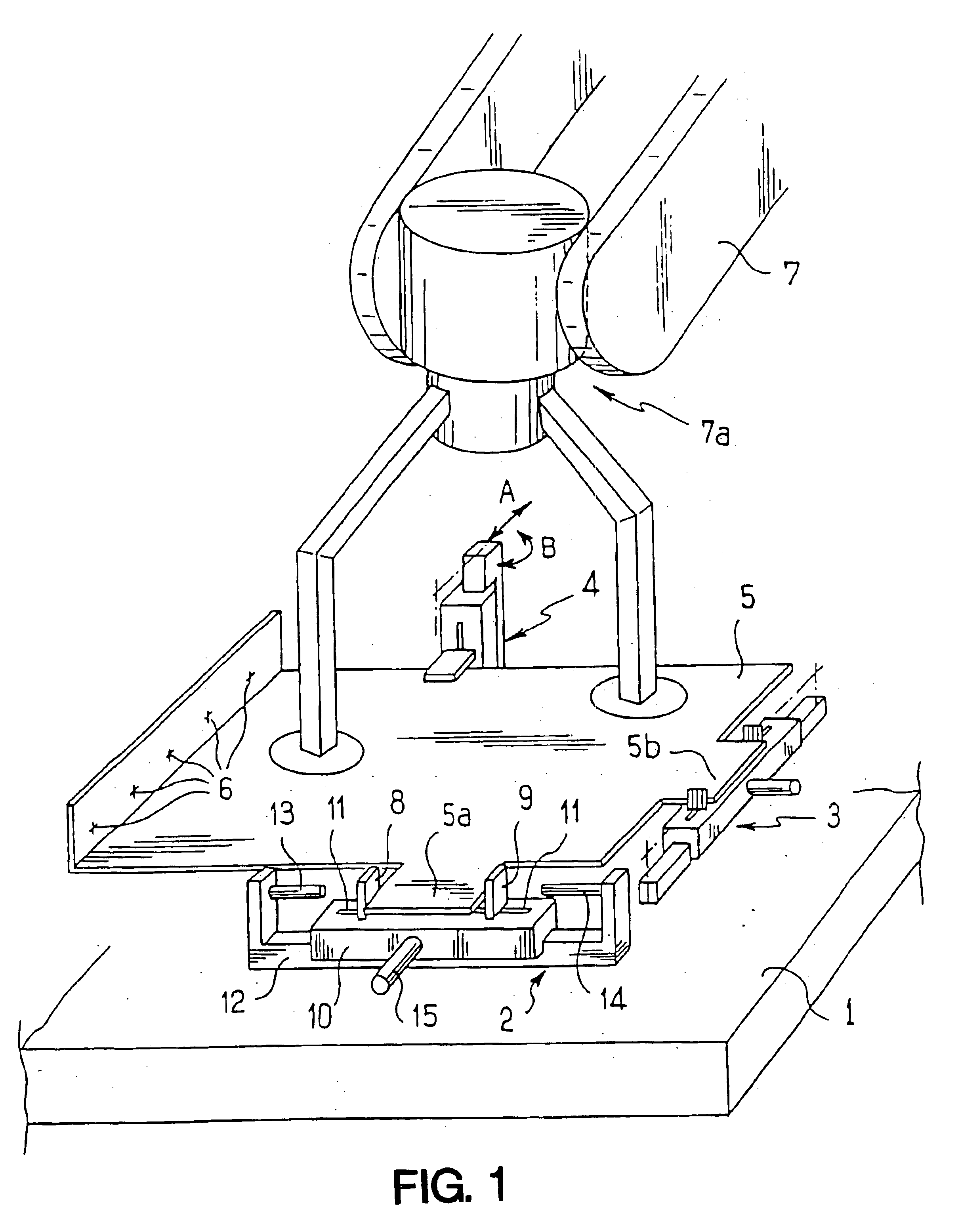
In FIG. 1, a table 1 represents the basic structure of an assembly station. Three clamping means 2, 3, and 4 are placed on the table together with a metal sheet 5 that is to be assembled, e.g. via spot welds 6, to another part placed in the assembly station and not shown. The metal sheet 5 is brought into the frame of reference of the assembly station and is positioned accurately therein by a robot 7 represented diagrammatically merely by a grip 7a to which the part 5 is coupled by known means (clip fastening, suction cup, . . . ).

For explanatory purposes, the part 5 is shown as having two side tongues 5a and 5b which are used for clamping the part in a plane parallel to the plane of the support 1 of the assembly station.

Also for reasons of explanation, each of the clamping means is shown as being in the form of a clamp, and comprising for the means 2, for example: two jaws 8 and 9 slidably mounted in a body 10 having slideways 11 and capable of being moved apart from or towards eac...


PUM


Abstract

A method of holding a part (5, 16) in position in an assembly station (1), in which the part (5) is put into a determined position in the frame of reference of the assembly station (1) by way of a handling robot (7), at least one clamp (2, 3, 4) is closed onto a portion (5a, 5b) secured to the part, the clamp being mounted to slide freely in a guide (12) of the assembly station (1) extending parallel to its own clamping direction, and the clamp is blocked against sliding when it is clamped onto the part.

Description

In methods of assembling parts together, in particular automotive bodywork parts, it is common practice to bring the various parts for assembly to an assembly station where they are firstly put accurately into position relative to one another, and secondly they are held in position firmly so as to ensure that any forces applied to them by the assembly tooling (welding clamps in particular) do not disturb, alter, or modify their intended positions and thus the general shape of the assembly once it has been made.BACKGROUND OF THE INVENTIONAn assembly station is fed with parts for connecting to one another by a handling tool (a robot) which “entrusts” the part it is transporting to tooling specific to the assembly station, which tool then ensures that the part is put accurately into place and is clamped firmly in place. That conventional disposition suffers from the major drawback of requiring the assembly station to implement tools that are dedicated to each of the parts received. Con...

Claims


Application Information

Patent Timeline
IPC IPC(8): B23K37/04
CPCB23K37/0443Y10T29/53961
Inventor BIDAUD, DANIEL
Owner ABB BODY & WHITE
Why Eureka
Try Eureka