Keeper for positioning ring seals

a technology of positioning rings and seals, which is applied in the direction of machine/engine, cable terminations, manufacturing tools, etc., can solve the problems of manual positioning of seals between mating surfaces, difficulty in establishing fluid or gaseous seals, and particularly troublesome problems

Inactive Publication Date: 2005-01-25
MICROFLEX TECH INC
View PDF12 Cites 61 Cited by
  • Summary
  • Abstract
  • Description
  • Claims
  • Application Information

AI Technical Summary

Benefits of technology

The present invention addresses the aforementioned disadvantages by providing an improved keeper for positioning ring seals between opposed mating surfaces. The keeper, similar to previous keeper constructions includes a substantially planar sheet including an upper surface and lower surface. The upper surface of the planar sheet is intended for engaging a first mating surface, while the opposed lower surface is intended for engaging a second mating surface. The planar sheet further includes one or more holes wh

Problems solved by technology

When the ring seals are small in size, it is extremely difficult to manually position them properly between mating surfaces.
This problem is particularly troublesome when trying to position numerous ring seals adjacent to one another between a single pair if mating surfaces.
As a result, a

Method used


Image

  • Keeper for positioning ring seals
  • Keeper for positioning ring seals
  • Keeper for positioning ring seals

Examples


Embodiment Construction

While the present invention is susceptible of the embodiment in various forms, as shown in the drawings, hereinafter will be described the presently preferred embodiments of the invention with the understanding that the present disclosure is to be considered as an exemplification of the invention and it is not intended to limit the invention to the specific embodiments illustrated.

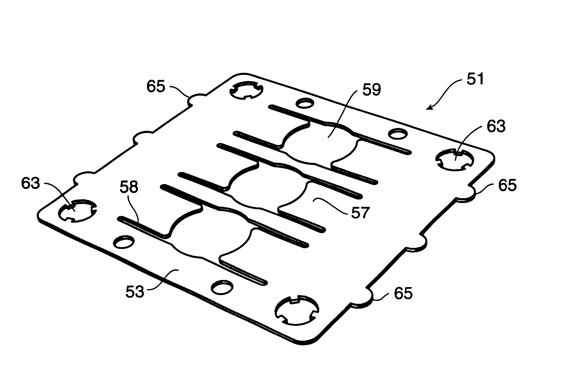
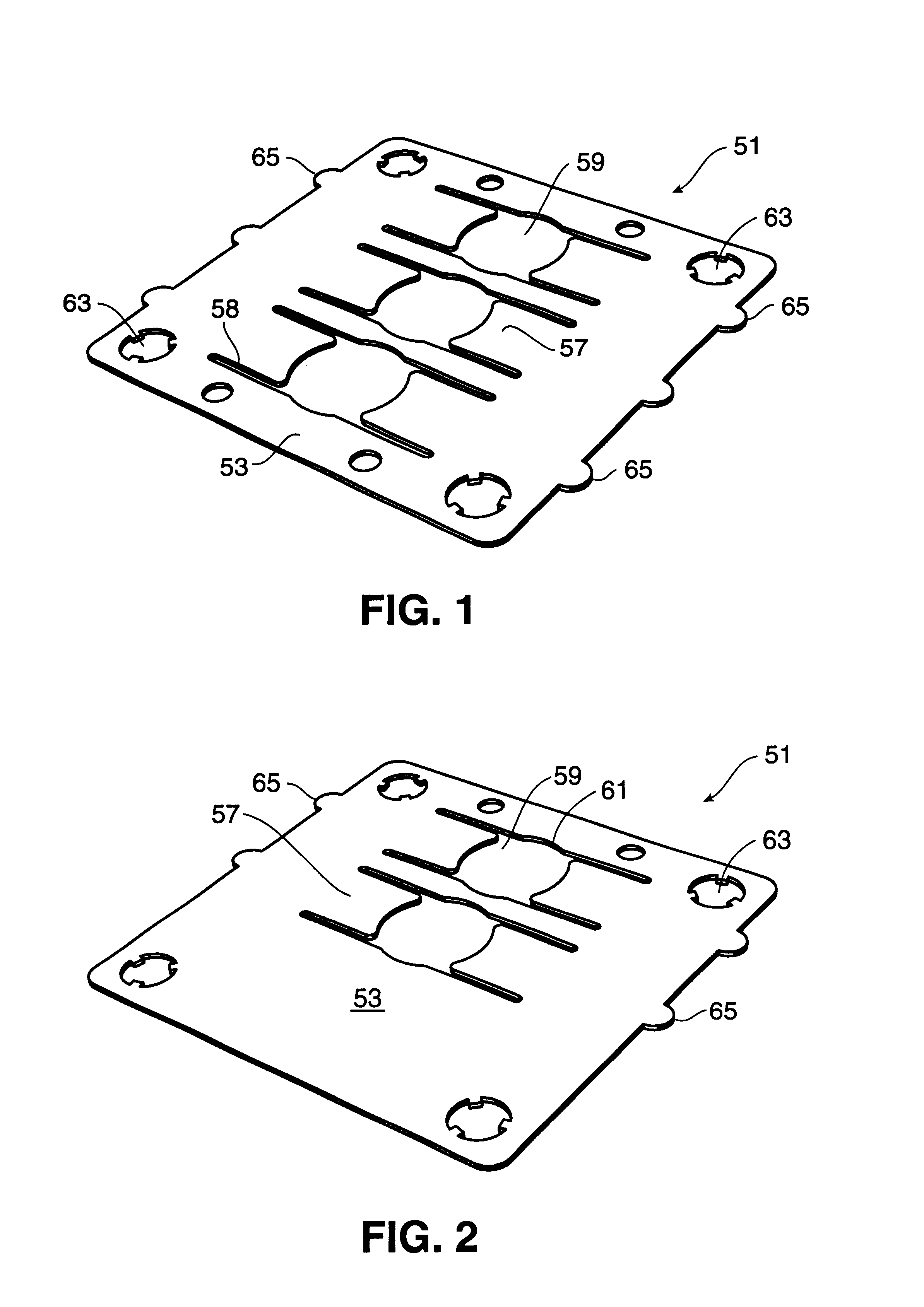
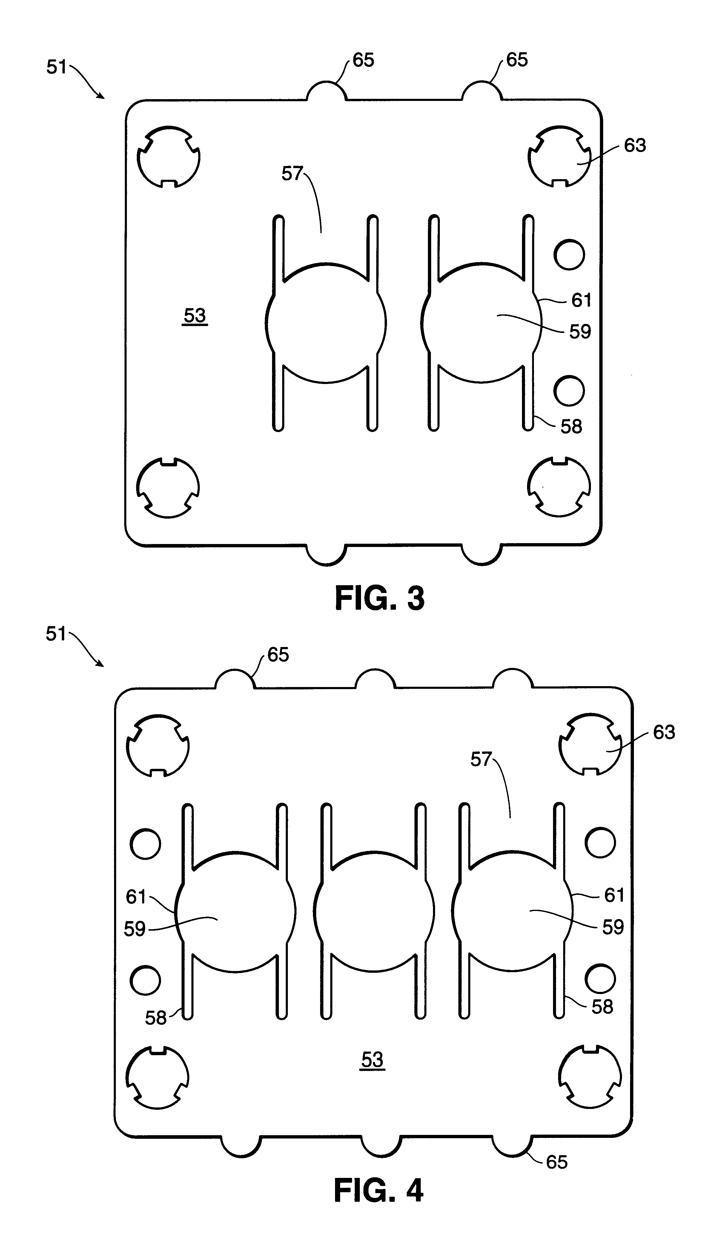
With reference to the figures, the present invention is directed to a keeper 51 for positioning ring seals 1 between mating surfaces 31. The keeper 51 of the present invention is preferably constructed of a planar sheet having an upper surface 53 and a lower surface (not shown). The keeper may be constructed of various materials, as can be selected by those skilled in the art. Metals and alloys exhibiting limited thermal expansion and non-corrosive properties such as alloys including aluminum, copper, silver, nickel, hastelloy or stainless steel are preferred.

As shown in the FIGS. 1-5, the keeper 51 may be...


PUM


Abstract

An improved keeper for positioning ring seals is provided. The keeper includes a substantially planar sheet defining upper and lower surfaces. Projecting through the planar sheet are one or more holes configured for affixing corresponding one or more ring seals. The keeper further includes one or more nodes which extend outwardly from the planar sheet beyond the dimensions of the mating surfaces between which a sealed joint is obtained. The one or more nodes identify the position and number of holes constructed for receiving corresponding ring seals.

Description

BACKGROUND OF THE INVENTIONThe present invention relates to keepers which are used to position ring seals between opposed mating surfaces.Ring seals, often referred to as gaskets, are compressed between mating surfaces for making a gaseous or fluid-tight seal sealed joint between the opposed mating surfaces. Ring seals include simple “O rings”, and also include “C seals”, “V seals”, and “Z seals”. A C seal is circular and constructed with a radial cross section having a “C” shape. These C seals are constructed both with the open side of the C construction facing the center of the ring, and with the open side of the C seal facing away from the center of the ring. As two parallel mating surfaces are brought together with the C seal in the middle, the seal is compressed with the open side of the C cross section closing during compression. The ductile properties of the ring seal permit plastic deformation to occur without damaging the mating surface. To increase the elastic recovery of ...

Claims


Application Information

Patent Timeline
IPC IPC(8): B25B27/00F16J15/06
CPCF16J15/061B25B27/0028
Inventor DOYLE, MICHAEL
Owner MICROFLEX TECH INC
Why Eureka
Try Eureka