Security cover system for cargo container latch

a security cover and cargo container technology, applied in the field of latches, can solve the problems of 008 suffering the problem of shanks or shackles being exposed to bolt cutters or other shears, and the task of securing such containers against break-ins has proved difficult to solv

Inactive Publication Date: 2005-01-25
SECURUS ENTERPRISES
View PDF14 Cites 25 Cited by
  • Summary
  • Abstract
  • Description
  • Claims
  • Application Information

AI Technical Summary

Benefits of technology

It is therefore a general object of the present invention to provide an improved security system for cargo container latches.
A further object is to provide a cargo latch security system which does not expose any portion of the shank of the pin, when secured to the container.
Yet another object is to provide an improved security system for a cargo latch which is simple and economical to manufacture.
The security system for a shipping container of the present invention includes a cover and seal pin, and a special removal tool for removing the pin from the cover. The cover includes a vertical channel with top and bottom plates mounted therein to form a rearwardly opening box. A pair of vertically aligned apertures in the top and bottom plates are aligned with apertures in ears of a hasp on the shipping container, and receive the seal pin to secure the cover to the container. The seal pin includes an elongated shaft with annular grooves in the upper and lower ends. A pair of end caps each includes an annular groove on their interior surfaces that correspond with the shaft grooves to retain a locking ring within the pair of aligned grooves, when the caps are snapped on the ends of the shaft. The locking rings prevent removal of the caps, once snapped into place on the shaft. The removal tool includes a hydraulic pump with a punch secured to a piston of the pump. A punch housing has a gripping structure on the lower end that will grip a seal pin end cap, while the punch is driven through the end cap to push the shaft free of the end cap and release the seal pin.

Problems solved by technology

However, the task of securing such containers against break-ins has proven difficult to solve.
Although this apparatus provides protection for the hasp, it still leaves the shank of the security seal / pin open for tampering or cutting, through the openings in the front face.
Similarly, padlock-type security devices such as those disclosed in U.S. Pat. Nos. 5,477,710, 5,146,771 and 4,898,008 suffer the problem of exposure of the shanks or shackles to bolt-cutters or other shears.
This exposed locking body can therefore be accessed by unauthorized persons, and potentially permit tampering and prying of the locking body off the shank of the pin.

Method used


Image

  • Security cover system for cargo container latch
  • Security cover system for cargo container latch
  • Security cover system for cargo container latch

Examples


Embodiment Construction

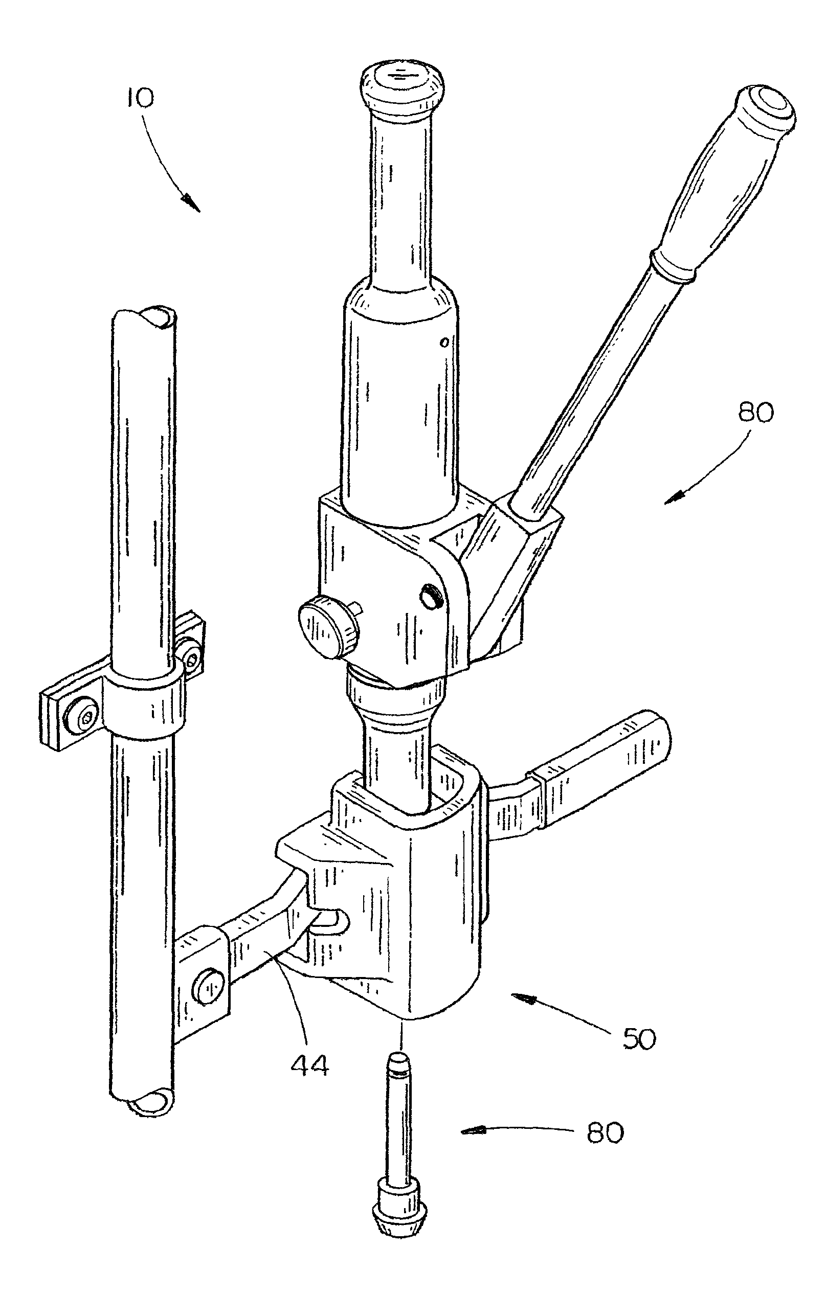
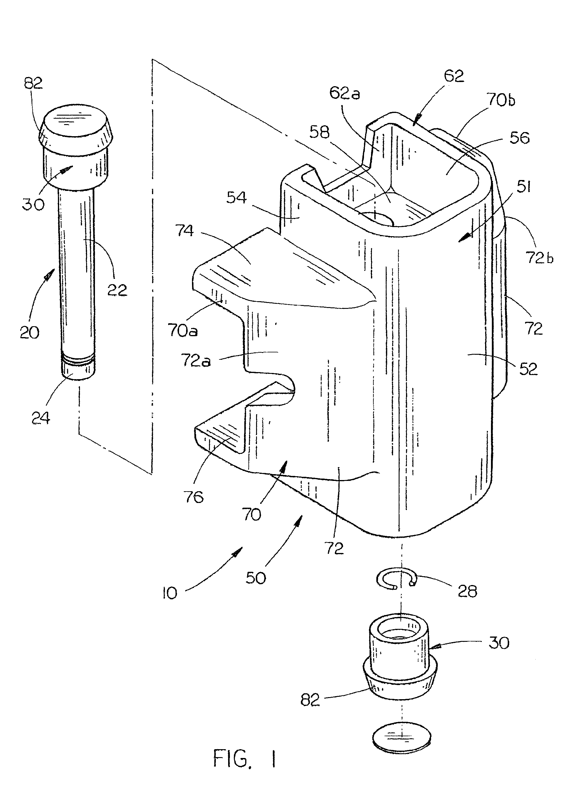
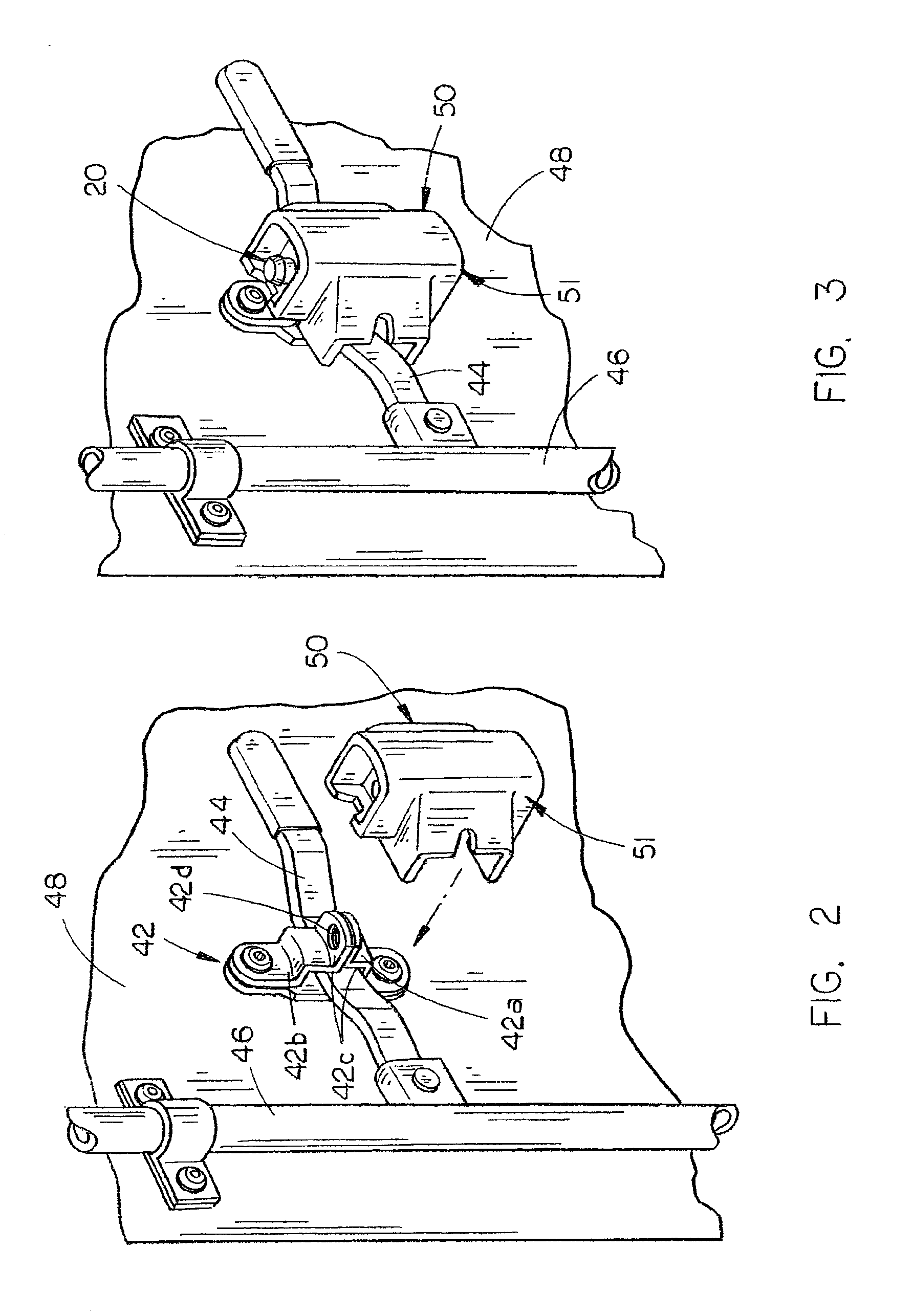
Referring now to the drawings, in which similar or corresponding parts are identified with the same reference numeral, and more particularly to FIGS. 1 and 10, the security system of the present invention is designated generally at 10 and includes three main components, namely, a seal pin 20, a security cover 50 and a removal tool 80.

Referring to FIGS. 1 and 6, the seal pin 20 is shown in detail. Seal pin 20 is preferably formed of a hardened steel or similar material which is not easily bent, cut or broken. Seal pin 20 includes an elongated cylindrical shaft 22 with identical opposing ends 24. Ends 24 are tapered to form a slightly conical shape, with a decreasing cross-sectional diameter at the extreme ends.

An annular groove 26 is formed around the circumference of the shaft adjacent each end 24, and located at the inward end of each tapered surface. Each groove 26 will receive a locking ring 28 therein, to retain end caps 30 in position on ends 24, as described in more detail her...


PUM


Abstract

A security system for a shipping container includes a cover and seal pin, and a special removal tool for removing the pin from the cover. The cover includes a vertical channel with top and bottom plates mounted therein to form a rearwardly opening box. A pair of vertically aligned apertures in the top and bottom plates are aligned with apertures in ears of a hasp on the shipping container, and receive the seal pin to secure the cover to the container. A seal pin includes an elongated shaft with annular grooves in the upper and lower ends. A pair of end caps each includes an annular groove on their interior surfaces that correspond with the shaft grooves to retain a locking ring within the pair of aligned grooves, when the caps are snapped on the ends of the shaft. The locking rings prevent removal of the caps, once snapped into place on the shaft. A removal tool includes a hydraulic pump with a punch secured to a piston of the pump. A punch housing has a gripping structure on the lower end that will grip a seal pin end cap, while the punch is driven through the end cap to push the shaft free of the end cap and release the seal pin.

Description

STATEMENT AS TO RIGHTS TO INVENTIONS MADE UNDER FEDERALLY SPONSORED RESEARCH AND DEVELOPMENT(Not applicable)BACKGROUND OF THE INVENTION1. Field of the InventionThe present invention relates generally to apparatus for securing the latch of a shipping container, and more particularly to an improved security cover system for preventing unauthorized access to a shipping container.2. Background InformationShipping containers are widely used in the transportation of various types of goods, both domestically and internationally. However, the task of securing such containers against break-ins has proven difficult to solve.Prior art attempts include such devices as hasp protectors and various bolt seals. For example, U.S. Pat. No. 5,118,149 discloses a container hasp protector with a metal box with an open rearward side. A shield plate on the front face extends between the sides to form upper and lower openings in the face between the shield plate and the top and bottom walls of the box. The...

Claims


Application Information

Patent Timeline
Patent Type & Authority Patents(United States)
IPC IPC(8): E05B67/38E05B67/00E05B39/00F15B15/18F15B15/00E05B65/12E05B65/16
CPCE05B39/00F15B15/18E05B67/38E05B83/10Y10T292/25Y10T292/51Y10T292/31Y10T292/48
Inventor PALZKILL, RAYMOND G.
Owner SECURUS ENTERPRISES
Why Eureka
Try Eureka