Rear-projecting device

a technology of rear projection and projection device, which is applied in the direction of identification means, instruments, lighting and heating apparatus, etc., can solve the problems of large compactness and achieve the effect of high standard maintenan

Inactive Publication Date: 2005-01-25
3D SYST INC +1
View PDF14 Cites 86 Cited by
  • Summary
  • Abstract
  • Description
  • Claims
  • Application Information

AI Technical Summary

Benefits of technology

A further advantage of the invention is that the light guide separation between the projection area and the light source(s) offers the possibility of high standard maintenance as the light source(s) may be located at an easily accessible position.
It should be noted that an easily accessible light source is of great importance during normal maintenance as the light source and the supporting circuitry are the most vulnerable and service-requiring parts of the projecting system. Moreover, an outdoor system such as a traffic sign is usually inaccessible as it is e.g. elevated substantially across intersections / highways. Hence, a remote positioning of the light source favors service personnel and engineers.
Moreover, alignment and calibration may be performed in two separate processes. The light guides may be calibrated with respect to the light modulating modules in a lab allowing the fitting personnel to subsequently calibrate the light source system to the input end of the light guides.
A further feature of the embodiment of the invention is that traditional replacement of the light source may be performed by low-skilled service personnel.
A further feature of the invention is that the utilization of light guides offers the possibility of sharing one light source between all modules of the system. Hence, the light may be distributed uniformly towards the involved modules. Basically, this feature means that complicated calibrations may be performed in a lab as homogeneous distribution may be obtained and calibrated by means of a proper design of the light guide system between the light source and the light modulating modules.
According to the invention, the device offers very advantageous modular features, as the light source(s) may be separated from the modulating arrangements and the projection areas in such a manner that the light source and the light-projecting components constitute two separate parts of the system which may be designed and calibrated more or less individually.

Problems solved by technology

Furthermore, the obtained reduction of distance between modules and the projection area results in a larger degree of compactness.

Method used


Image

  • Rear-projecting device
  • Rear-projecting device
  • Rear-projecting device

Examples


Embodiment Construction

Initially, some of the basic features of the invention will be described with reference to FIGS. 1A, 1B, 2A and 2B.

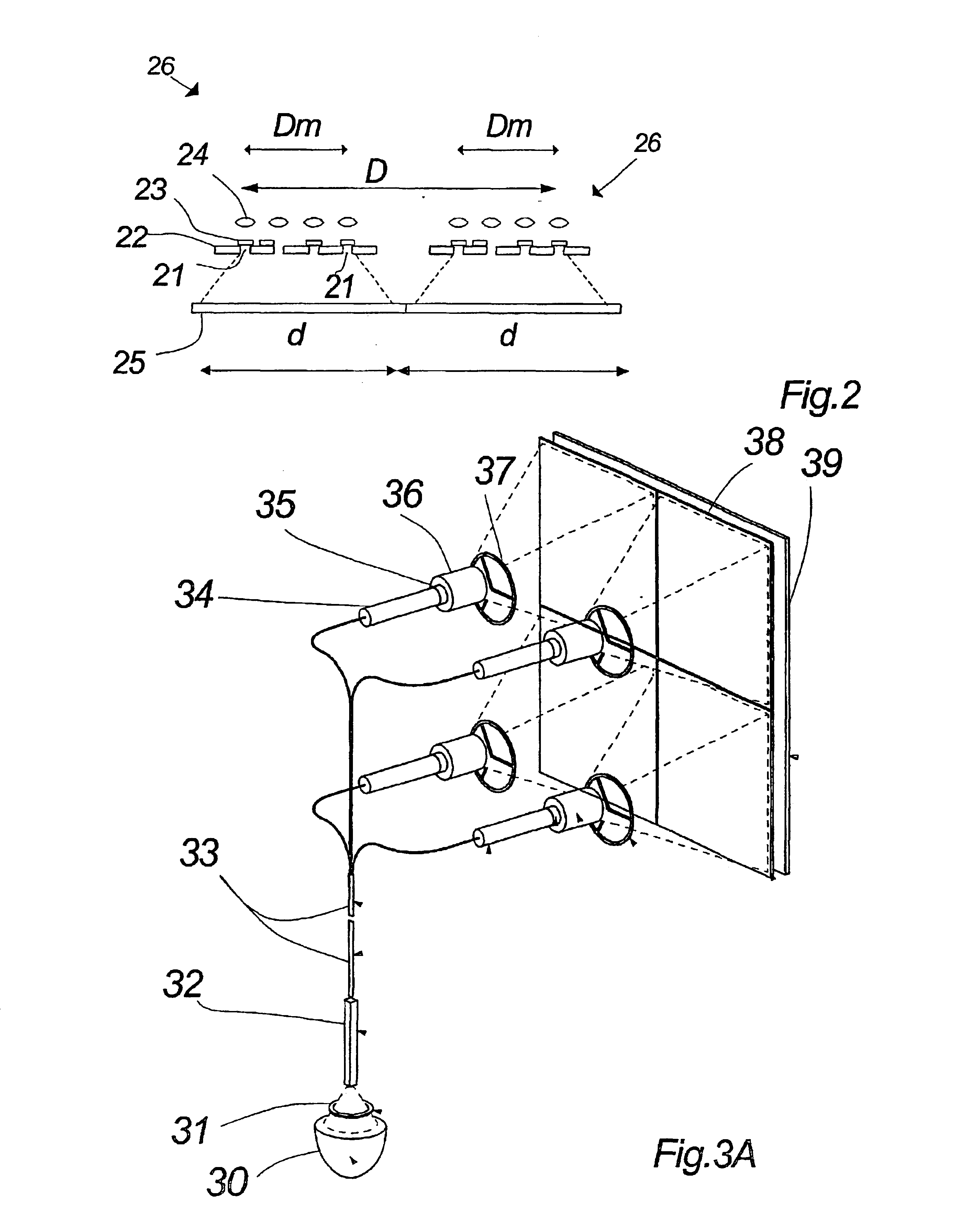
Subsequently, a preferred embodiment of the invention will be described with reference to FIGS. 3 to 5.

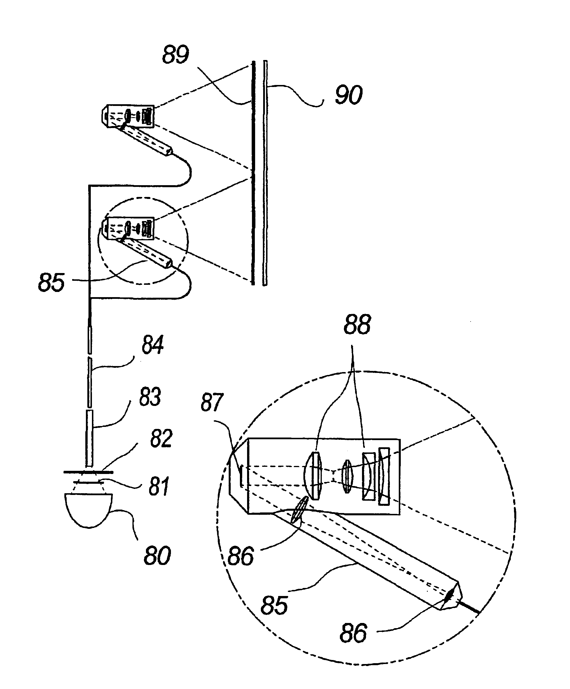
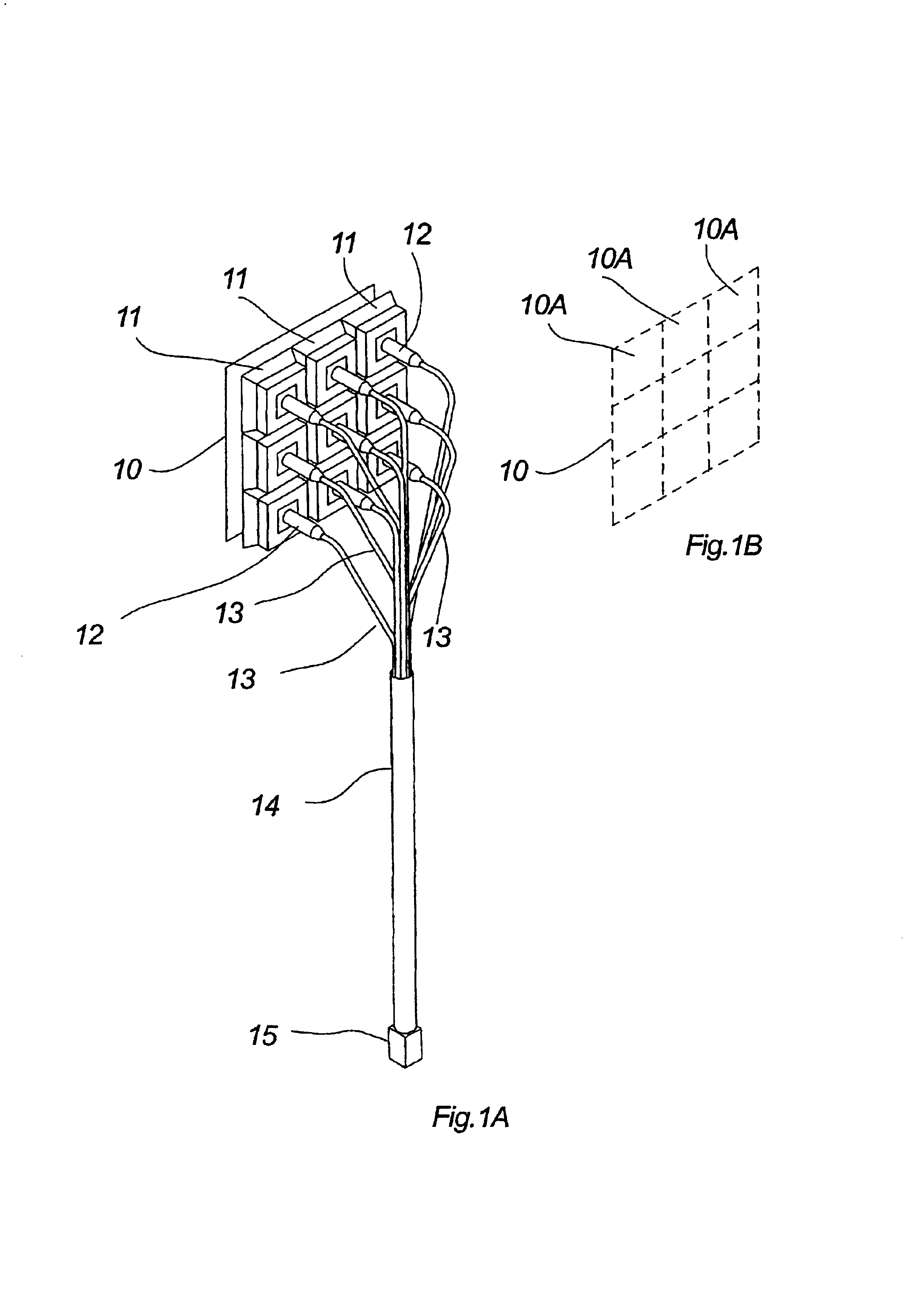
FIG. 1 shows a preferred embodiment of a rear-projecting arrangement according to the invention. The shown rear-projecting arrangement comprises a light receiving mixing rod 15. The mixing rod 15 is optically coupled with a bundle of optical fibers 13. Each of the optical fibers 13 comprises a light-emitting end in the form of an optical plug 12. Each of the plugs 12 is fixated for illumination of a spatial light modulating array (not shown) incorporated in a housing 11. The housings 11 are all arranged in fixed positions in relation to a transparent display 10.

It should be noted, that the mixing rod is optional and preferably applied when dealing with several light guides.

The display comprises a Fresnel lens and a diffuser (not shown).

The basic function of the rear-pr...


PUM

PropertyMeasurementUnit
transparentaaaaaaaaaa
areaaaaaaaaaaa
luminanceaaaaaaaaaa

Abstract

The invention relates to a rear-projecting device including a light guide for distribution of light from a light source to a light projecting area, a spatial light modulating arrangement, the light modulating arrangement is arranged in relation to the light-projecting area such that the arrangement illuminates a sub-area of the light-projecting area, the light projection area is at least partly transparent.

Description

FIELD OF THE INVENTIONThe invention relates to a rear-projecting device and, particularly, to a rear-projecting device for illuminating an area of a light projecting area.BACKGROUND OF THE INVENTIONAn example of a rear-projecting device is within the technical area of traffic signs.The area of traffic signs represents a technical area within which many attempts to modernize the traditional signing have more or less failed due to various circumstances.Hence, the traditional mechanically based traffic sign having one static painted signaling surface represents the dominating traffic sign of today.Nevertheless, several attempts of breaking the dominance of the above-mentioned technique have been made due to the fact that an effective variable traffic sign would provide immense improvements in regard to traffic control.One of the frequently used types of variable traffic signs comprises small rotatable mechanical elements having e.g. three different surfaces, each surface being dedicate...

Claims


Application Information

Patent Timeline
Patent Type & Authority Patents(United States)
IPC IPC(8): H04N9/12H04N9/31G02F1/1335G09F9/30
CPCG02F1/13336H04N9/12H04N9/3197H04N9/3147H04N9/3114
Inventor GLENT-MADSEN, HENRIKMEYER, S.O SLASHED.REN CHRISTOPHRAAHAUGE, KIM NIELS
Owner 3D SYST INC
Why Eureka
Try Eureka