Radius end mill having radius edge enhanced in resistance to chipping and fracture

a technology of radius end mill and discharging performance, which is applied in the field of improving the radius end mill, can solve the problems of increasing the contact frequency of the cutting edge with the workpiece, promoting wear, and unable to achieve a high cutting speed of the ball-nose end mill, so as to achieve enhanced resistance to the fracture of the r edge, the effect of high-feed cutting and enhanced discharging performan

Inactive Publication Date: 2005-01-25
HITACHI TOOL ENG LTD
View PDF9 Cites 70 Cited by
  • Summary
  • Abstract
  • Description
  • Claims
  • Application Information

AI Technical Summary

Benefits of technology

The present invention has been implemented in view of the foregoing situation, and has an object to provide a radius end mill which can suppress chipping and fracture of corner R edges to enable high-feed cutting.
Still furthermore, according to the present invention, the resistance of the outer peripheral edge to chipping and fracture can be enhanced with keeping high machinability of the R edge, and the high-feed cutting can be performed more stably.

Problems solved by technology

In addition, it is impossible to achieve a high cutting (milling) speed for the ball-nose end mill because the tip portion of the ball-nose end mill is located on the tool rotation axis of the ball-nose end mill.
Therefore, the contact frequency of a cutting edge with a workpiece is increased and wear is promoted.
However, only this method reduces the feed proportionally, and at any rate the working efficiency is lowered.
However, the radius end mill has had such a problem that when the feed per tooth is extremely increased, the cutting load is concentrated to corner R edges and the mechanical strength of the corner R edges is unendurable to the cutting load, so that the corner R edges are chipped or fractured and come to the ends of their lives.
Particularly, when the high-feed cutting is carried out in a cutting working needing a large cutting amount such as a rough working or the like, the cutting force is large and the chipping further easily occurs, so that the cutting condition must be loosened.
This means that the present cutting condition has not yet reached the high-efficiency cutting.

Method used


Image

  • Radius end mill having radius edge enhanced in resistance to chipping and fracture
  • Radius end mill having radius edge enhanced in resistance to chipping and fracture
  • Radius end mill having radius edge enhanced in resistance to chipping and fracture

Examples


first embodiment

[First Embodiment]

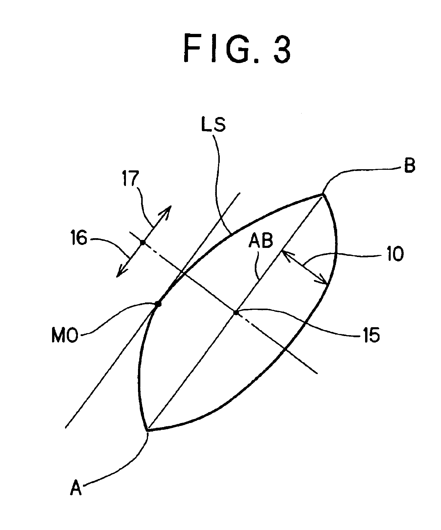
Now, a first embodiment according to the present invention will be described with reference to FIG. 3.

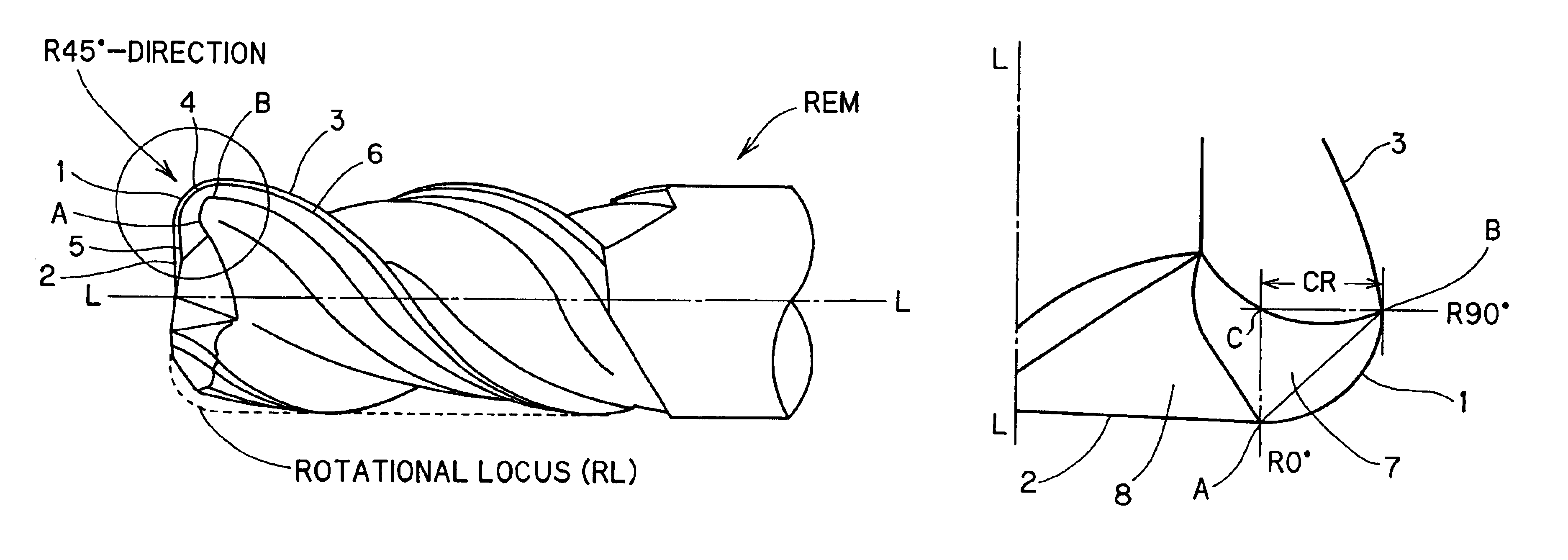
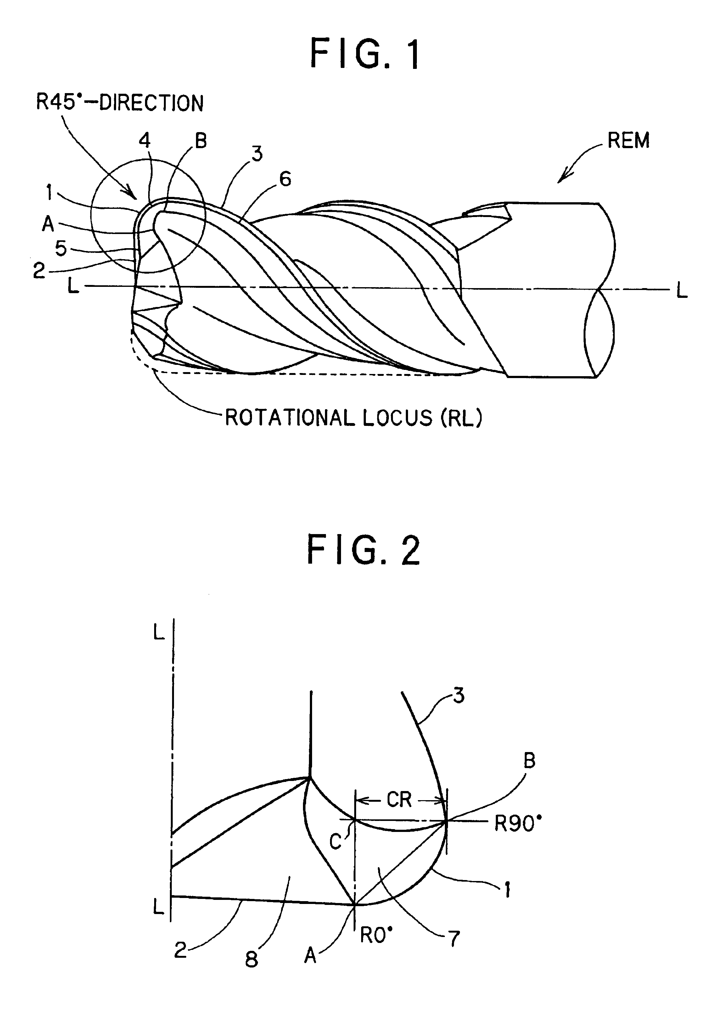
FIG. 3 is an enlarged cross-sectional view of a corner portion of the radius end mill REM according to the first embodiment, which contains the line AB connecting the connecting points A and B, and corresponds to a plan view which is viewed from the side of the rake face 7 of the radius edge 1.

In this embodiment, the cross-section view of the corner portion of the radius end mill REM in FIG. 3 is achieved by cutting the corner portion of REM along a plane which passes through the two connecting points A and B (i.e., contains the line segment AB connecting the connecting points A and B) so as to intersect to the rake face 7 of the R edge 1. The cross-sectional view thus achieved will be hereinafter referred to as “R cross-sectional view”). According to this embodiment, the surface shape of the rake face 7 of the R edge 1 is designed so that the line shape 7′ of the ...

second embodiment

[Second Embodiment]

The radius end mill according to a second embodiment of the present invention is characterized in that a surface constituting the rake face 7 of the R edge 1 is designed to have a convex curved surface in the direction from the R90° site to the R0° site as shown in FIG. 4, and also the end gash face (the rake face of the bottom edge 2) 8 extending from the R0° site to the tool rotation axis (A—A) is substantially flat.

As described above, the chips generated at the R edge 1 are discharged along the rake face 7. According to this embodiment, in order to reduce the contact direction of the rake face 7 with the chips and lower the cutting force, the face constituting the rake face 7 of the R edge 1 is designed to have a convex curved surface in the direction from the R90° site to the R0° site. With this design of the rake face 7 of the R edge 1, the cutting stress against the rake face 7 can be prevented from concentrating to one direction and thus dispersed in all di...

example 2

A radius end mill in which the rake angle was set to a negative angle in both the R normal-line direction and the tool radial direction from the R90° site to the R0° site of the R edge 1 was manufactured in the same manner as the example 1, and the same cutting test as the example 1 was conducted on the radius end mill thus manufactured. As a result, in the example 2, the cutting stable was more stable, the tool wear width was further smaller and the machined surface was more excellent as compared with the example 1.


PUM

PropertyMeasurementUnit
angleaaaaaaaaaa
relief angleaaaaaaaaaa
widthaaaaaaaaaa

Abstract

In a radius end mill having a bottom edge formed on the end face thereof, a radius edge designed in a substantially quarter arc shape and formed at a corner portion thereof, and an outer peripheral edge formed spirally on the side surface thereof, the bottom edge and the radius edge being continuously connected to each other at a connecting point A while the radius edge is continuously connected to each other at a connecting point B, when a view taken along a plane that passes through the connecting points A and B and crosses a rake face of the radius edge is represented by an R cross-sectional view, the rake face of the radius edge is designed to have a convex curved line extending from the connecting point A to the connecting point B in the R cross-sectional view.

Description

BACKGROUND OF THE INVENTION1. Field of the InventionThe present invention relates to an improvement of a radius end mill used for a contour line engraving operation, etc. for metal molds, etc., and particularly to an improvement of a radius end mill used for high-feed cutting.2. Description of the Related ArtA ball-nose end mill has been generally used to subject metal molds, etc. to a contour line engraving operation. Recently, high-efficiency cutting has been strongly required, and a radius end mill has been more frequently used in place of the ball-nose end mill.As compared with the ball-nose end mill, the cutting edges of the radius end mill are brought into contact with a workpiece at a shorter length. In addition, it is impossible to achieve a high cutting (milling) speed for the ball-nose end mill because the tip portion of the ball-nose end mill is located on the tool rotation axis of the ball-nose end mill. On the other hand, it is possible to achieve a sufficiently high cu...

Claims


Application Information

Patent Timeline
Patent Type & Authority Patents(United States)
IPC IPC(8): B23C5/10
CPCB23C5/10B23B2228/52B23C2210/082B23C2210/084Y10T407/1946B23C2224/24Y10T407/1948Y10T407/1908Y10T407/1966B23C2210/48
Inventor KURODA, TAKAHITOOKANISHI, RYOSUKESAKAMOTO, YASUSHIMAEDA, KATSUTOSHI
Owner HITACHI TOOL ENG LTD
Why Eureka
Try Eureka