Image formation controlling method and image forming apparatus

a technology of image formation and control method, applied in the direction of electrographic process, instruments, specific gravity measurement, etc., can solve the problems of deteriorating image quality, difficult to attach a large-scale jig which requires accurate positioning, and change in the density of a formed image, etc., to achieve high-quality images

Inactive Publication Date: 2005-01-25
SHARP KK
View PDF12 Cites 23 Cited by
  • Summary
  • Abstract
  • Description
  • Claims
  • Application Information

AI Technical Summary

Benefits of technology

This image formation controlling method does not require a calibration plate for calibrating the image density sensor for detecting the quantity of light reflected at a toner pattern image, so that contamination of a standing calibration plate by toner does not occur.
Moreover, after replacement of one or a plurality of constituent parts of an image forming apparatus, such as an image density sensor, a photoconductor, an intermediate transfer drum or an intermediate transfer belt, and a transfer drum or a transfer belt, or when aging deterioration of performance of the image density sensor occurs, the image density sensor can be calibrated easily and precisely and the image density of a toner pattern image can be detected precisely irrespective of the state of the surface of the photoconductor, transfer member or the like.
Consequently, by controlling conditions for image formation reliably, the image density of a toner pattern image can be held proper and a high-quality image can be realized.

Problems solved by technology

A change in characteristic may cause a change in the density of a formed image and deterioration of image quality.
Moreover, since the image density sensor is arranged in a considerably narrow space, it is difficult to attach a large-scale jig which requires accurate positioning.
Such a state causes an increase in maintenance cost.
Furthermore, on the assumption that user maintenance is performed, it is extremely difficult to perform accurate calibration in view of complication of a calibration operation.
There is, however, a problem that structure becomes complex because of installment of a sliding mechanism of the calibration plate.
There is another problem that it is difficult to avoid contamination by toner due to long use in the image forming apparatus, which cause increase in maintenance cost.

Method used


Image

  • Image formation controlling method and image forming apparatus
  • Image formation controlling method and image forming apparatus
  • Image formation controlling method and image forming apparatus

Examples


Embodiment Construction

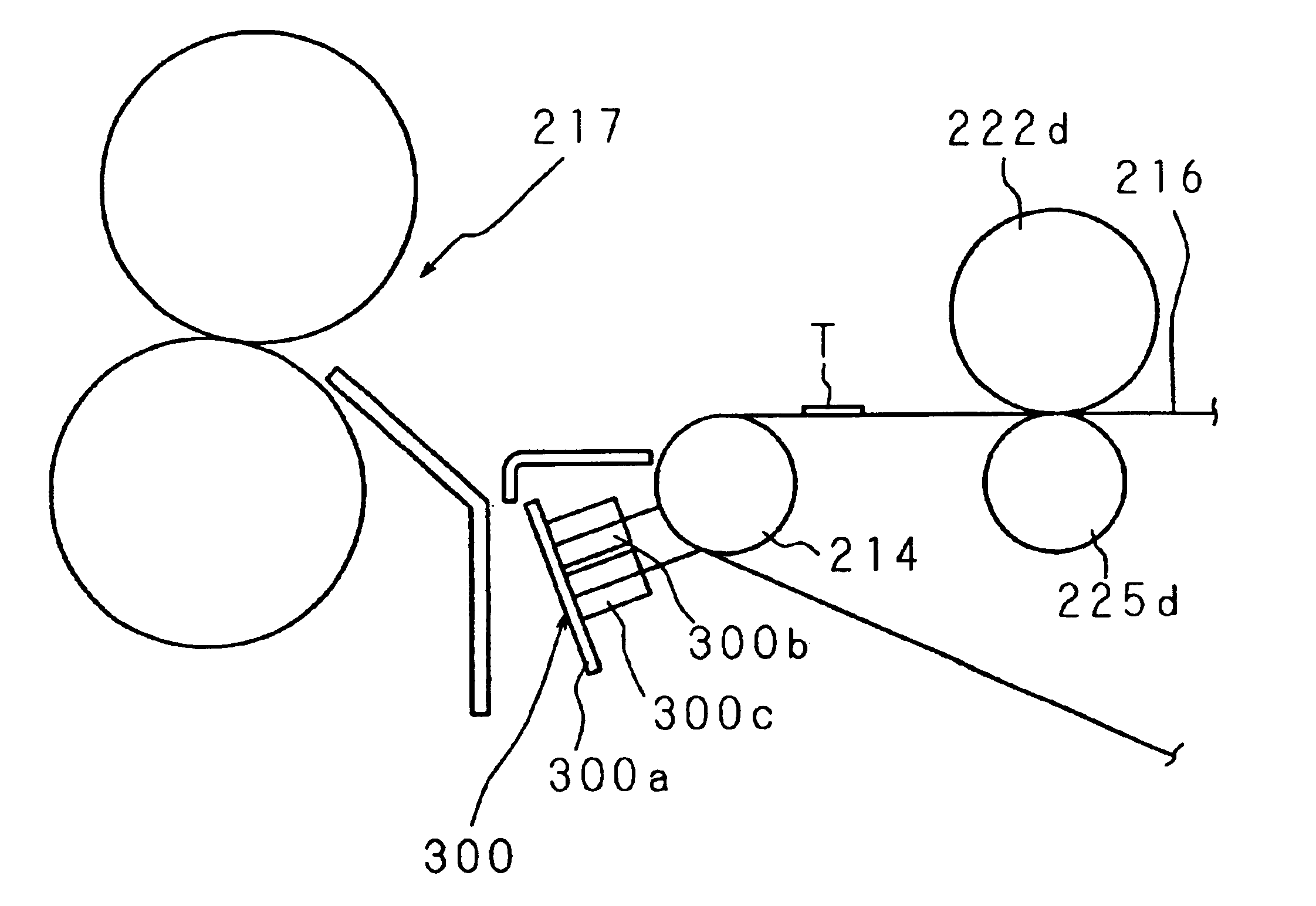
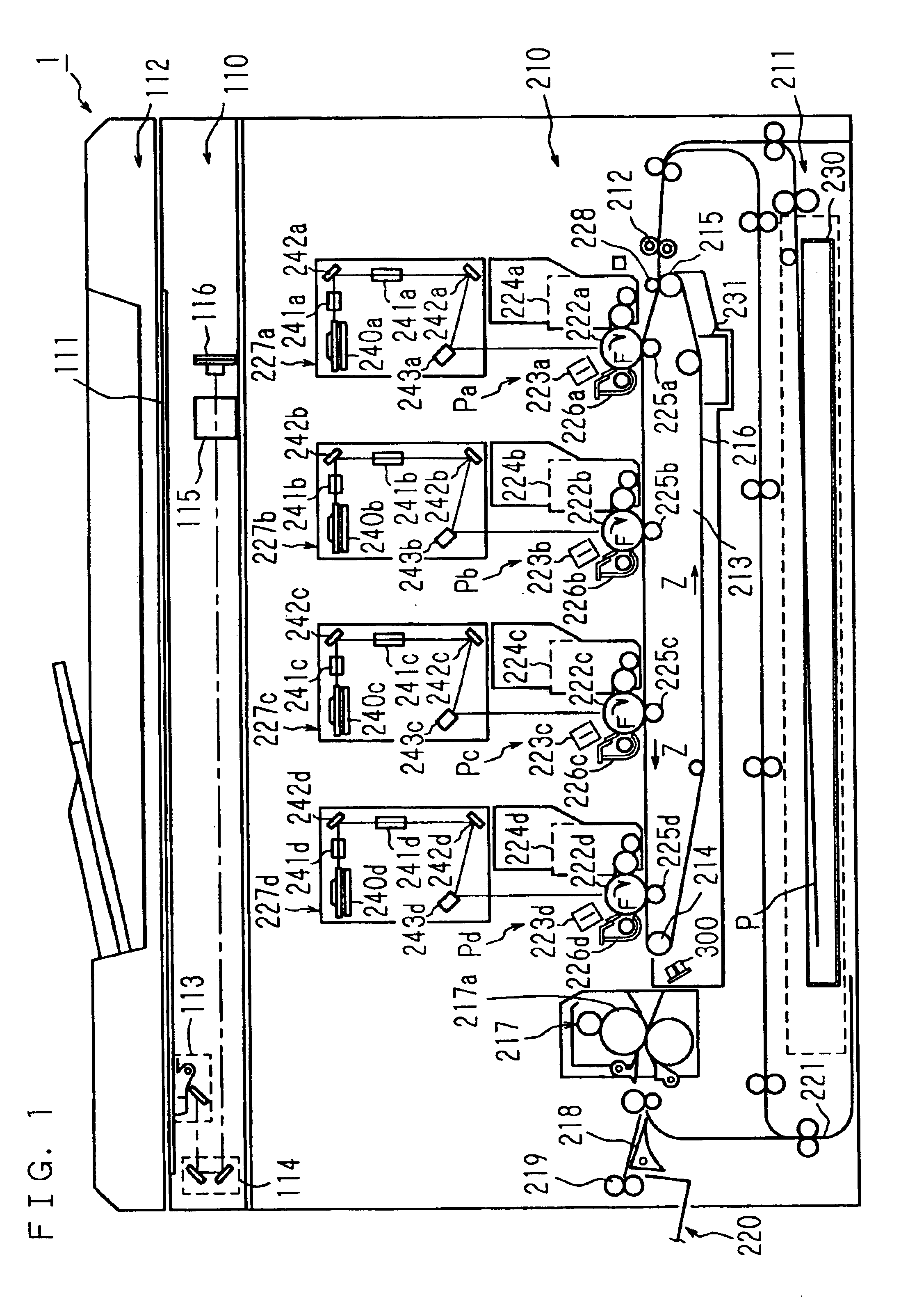
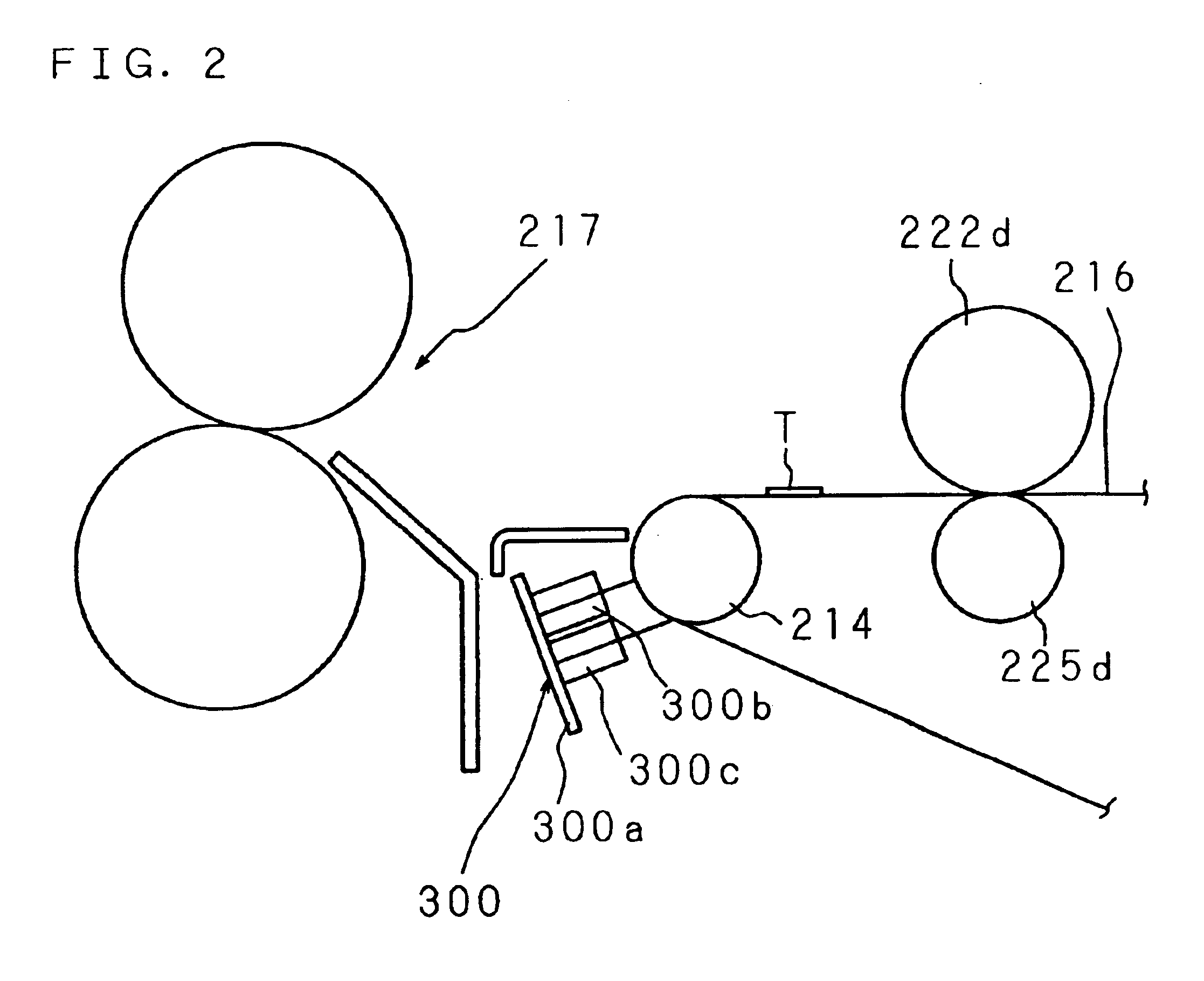
FIG. 1 is a schematic sectional front view showing the structure of a digital color copying machine 1 which is an image forming apparatus according to an embodiment of the present invention.

A document table 111 and an operation panel are provided at an upper portion of the copying machine body 1. An image reader 110 and an image forming section 210 are provided in the copying machine body 1.

Mounted on an upper face of the document table 111 is a reversing automatic document feeder (RADF) 112 which is supported so as to have a predetermined positional relation with the document table 111 and so as to be opened and closed.

The reversing automatic document feeder 112 transports a document so that a face of the document opposes the image reader 110 at a predetermined position of the document table 111. After reading of an image on the face of the document is completed, the reversing automatic document feeder 112 reverses and transports the document so that the other face of the document ...


PUM

PropertyMeasurementUnit
luminescence centre wavelengthaaaaaaaaaa
image densityaaaaaaaaaa
colorsaaaaaaaaaa

Abstract

Before replacement of constituent parts of an image density sensor or of other image forming units, the image density of a formed test toner patch image is detected by the image density sensor and conditions for image formation are controlled. After replacement of the constituent parts, the image density sensor detects the image density of a test toner patch image which is formed based on the controlled conditions for image formation. The optical output and/or the optical sensitivity is adjusted so that a detected value becomes a predetermined reference value, to calibrate the image density sensor. With this image formation controlling method, the image density sensor can be calibrated easily and precisely, the image density of a toner pattern image can be held proper and a stable high-quality image can be obtained.

Description

BACKGROUND OF THE INVENTION1. Field of the InventionThe present invention relates to an image formation controlling method comprising a step of calibrating (adjusting) an image density sensor for detecting the image density of a toner pattern image of each color, which is formed on a photoconductor, an intermediate transfer member or a transfer member of an image forming apparatus such as a copying machine or a printer of various kinds, and to an image forming apparatus used for performing the image formation controlling method.2. Description of Related ArtSince a photo type image forming apparatus forms an image using electrostatic force, the characteristic thereof is changeable in response to a change in conditions of each processing unit in use and conditions of surroundings. A change in characteristic may cause a change in the density of a formed image and deterioration of image quality. In order to avoid such a situation and to adjust image quality so as to keep obtaining prefe...

Claims


Application Information

Patent Timeline
Patent Type & Authority Patents(United States)
IPC IPC(8): G01N21/47G01N9/00G03G15/00G03G15/08G03G15/01G03G21/00H04N1/29H04N1/23H04N1/60
CPCG03G15/5058G03G15/0131G03G15/0194H04N1/6033G03G2215/00059G03G2215/0164G03G2221/1603
Inventor KITAGAWA, TAKASHIDAKESHITA, KAORIINO, TOSHIAKIYAMANAKA, TAKAYUKIKIDO, EIICHI
Owner SHARP KK
Why Eureka
Try Eureka