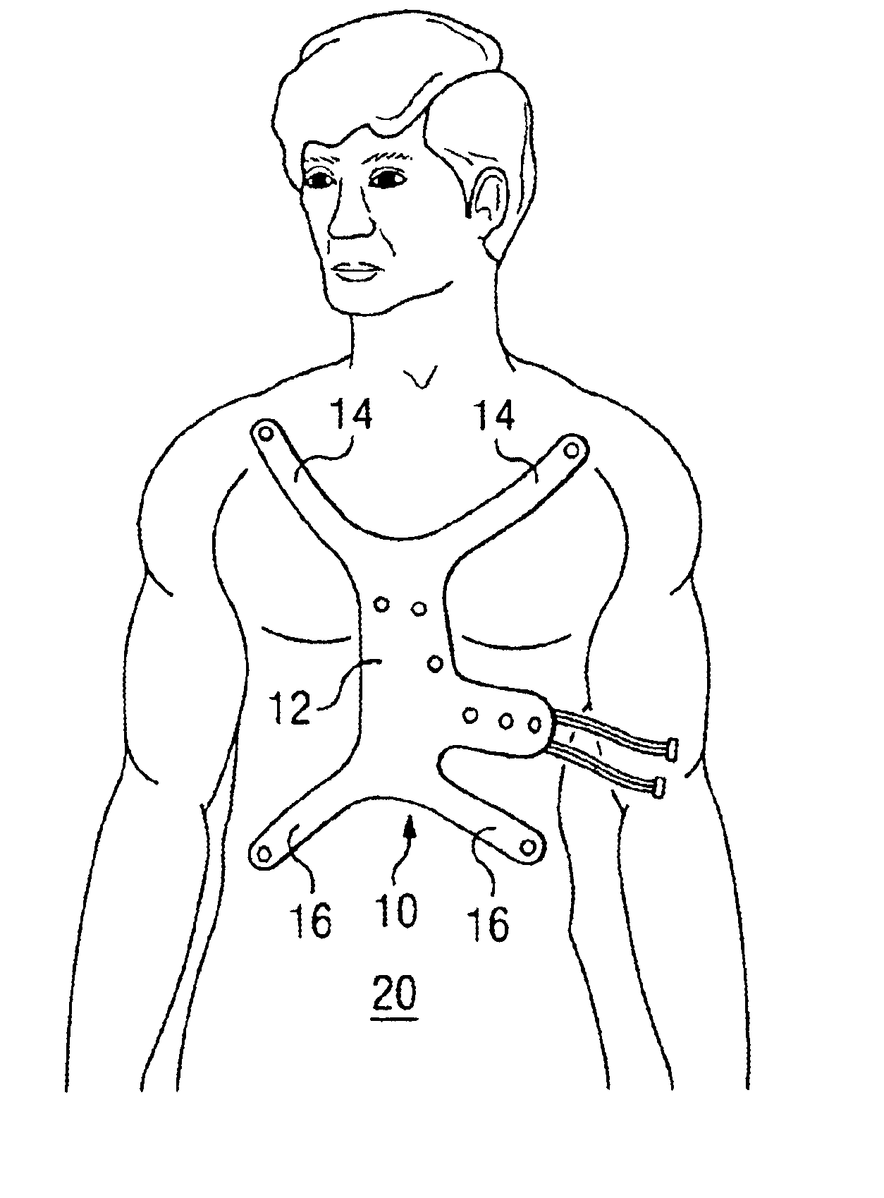
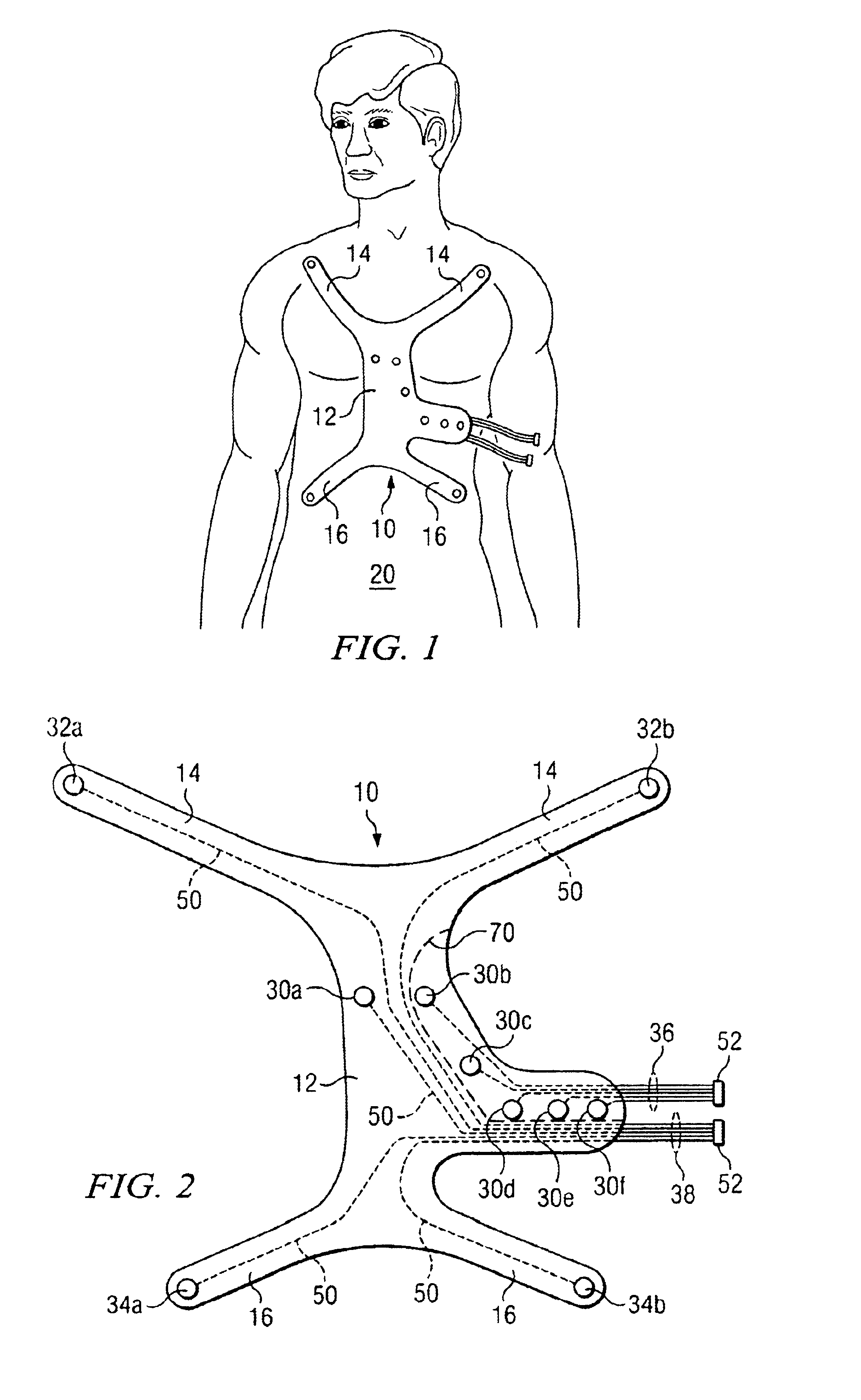
Emergency ECG electrode chest pad

a chest pad and electrode technology, applied in the field of electrocardiogram (ecg) diagnostic devices, can solve the problems of increasing the time required for attaching the ten or twelve electrodes and the corresponding leads, increasing the difficulty of additional emergency medical procedures, and increasing the time required for attaching, so as to eliminate clutter and time the effect of attaching

Inactive Publication Date: 2005-01-25
SUJDAK LENNY
View PDF15 Cites 194 Cited by
  • Summary
  • Abstract
  • Description
  • Claims
  • Application Information

AI Technical Summary

Benefits of technology

To attain the objects described above according to this invention, there is provided an ECG diagnostic pad comprising a pad base with upper fit portions with upper limb lead electrodes, a central fit portion with unipolar precordial lead electrodes and a lower portion with flank lead electrodes. The corresponding electrode wires, connecting the pad to the monitoring unit, are embedded in the pad internally to

Problems solved by technology

When such electric signals are irregular, it is a sign of cardiac problems, particularly cardiac arrest, better known as a “heart attack.”
The work of attaching the ten or twelve electrodes and the corresponding leads can be time consuming.
In addition, the leads tend to clutter up the chest area, making additional emergency medical procedures more difficult to perform.
Such problems associated with this process are increased when the patient is a small child or an infant.
As previously mentioned this process is cumbersome and time consuming, particularly within an emergency situation.
Under such circumstances, the electrodes may be incorrectly placed or fall off the patient, thus requiring additional time for replacement upon the patient.
However, such vests, including those seen in Mills and Sekine, have several drawbacks.
Production and acquisition costs are increased as well

Method used


Image

  • Emergency ECG electrode chest pad
  • Emergency ECG electrode chest pad
  • Emergency ECG electrode chest pad

Examples


second embodiment

FIGS. 5 and 6 illustrate the subject invention. In addition to the structures and features detailed in the preferred embodiment, it is contemplated that external pacer pads 100a and 100b can be added to the device. The external pacer pad 100a is located just below the right upper fit portion 14 of the pad 10 and external pacer pad 100b is located just below the horizontal central fit portion 12, which are the proper positions for the prescribed anatomical locations. Like an implanted pacemaker, pacer pads 100 and 100 serve to provide an electrical pulse to the heart to correct an irregular heartbeat. Pacer pads 100a and 100b are electrically connected to pacer control instrument 110 by way of wires 102a and 102b that form a pacer plug bundle 104. Although wires 102a and 102b can be embedded in the fabric of pad 10, the are preferably left free or retained to the exterior of the pad 10 by the minimal use of an adhesive such that the wires 102a-b can easily be moved or removed with th...

third embodiment

the invention is illustrated with reference to FIGS. 7 and 8. In addition to the structures and features detailed in the preferred embodiment, it is contemplated that defibrillator pads 200a and 200b properly positioned for the prescribed anatomical locations can be added to the ECG electrode pad 10. The defibrillator pad 200a is located just below the right upper fit portion 14 of the pad 10 and defibrillator pad 200b is located just below the horizontal central fit 12 portion of the pad 10. The defibrillator pads 200a and 200b are made of a flexible solid conductor gel to ensure contact with the patent and can be adhered to the patient as know in the art, consistent with the techniques used for the main ECG pad 10. If defibrillation of the patient is required, the physician can applied the defibrillation paddles of the defibrillator directly to pads 200a and 200b without use of separate conductor gel. As previously described in the primary embodiment of the inventive ECG pad, a pe...


PUM


Abstract

An ECG electrode chest pad particularly adapted for use in emergency room situations having upper fit portions with upper limb electrodes, and elongated central or medial base fit portion with a plurality of precordal unipolar electrodes and lower fit portions with lower limb electrodes, said electrodes being attached to leads which are internal to the base chest pad and terminate into at least one lead branch adapted to plug into an ECG monitor and having a perforation in the base pad material such that one group of electrodes may be separated from a second group of electrodes to facilitate ease of patient monitoring and complimentary medical procedures.

Description

BACKGROUND OF THE INVENTION1. Field of InventionThis invention relates to a electrocardiogram (ECG) diagnostic device, and more specifically, to a disposable ECG diagnostic chest pad having pre-positioned lead electrodes and internal wiring which may be placed quickly as a single unit upon a patient and may be separated into two sections by way of perforated sections in the underling pad material, thus allowing greater flexibility in monitoring and diagnosing a patient's electrocardiogram waves.2. Description of Prior ArtIt has been long known in the medical community that the current condition, and possibly future state, of a subject patient's heart muscle can be ascertained by measuring the cardiac electrical activity. The electrical system of the heart not only initiates and controls the rate of heartbeat, but also coordinate to transmission in the most efficient mechanical manner. When such electric signals are irregular, it is a sign of cardiac problems, particularly cardiac ar...

Claims


Application Information

Patent Timeline
IPC IPC(8): A61B5/0408
CPCA61B5/6841A61B5/04085A61B2562/17A61B5/282
Inventor SUJDAK, LENNY
Owner SUJDAK LENNY
Why Eureka
Try Eureka