Harmonic RFID Tag-Reader System For Long Range Sensing Identification And Security

Active Publication Date: 2019-11-28
BOARD OF TRUSTEES OPERATING MICHIGAN STATE UNIV
View PDF4 Cites 7 Cited by
  • Summary
  • Abstract
  • Description
  • Claims
  • Application Information

AI Technical Summary

Benefits of technology

[0047]FIG. 7 is a schematic of an example implementation of an interrogator 600. The interrogator 600 may be designed and developed to read out the tag ID from a harmonic RFID tag 602. For example, a stable frequency synthesizer 604 can generate a fundamental signal (f0) at 434 MHz. The f0 may be amplified to 18 dBm by using a power amplifier (PA) 608. As a receiving antenna 612 works at second harmonic (2f0) frequency, it is important to mitigate the transmission of harmonics, which are generated from the PA 608. A low-pass filter 616 with cut-off frequency of 500 MHz is used before feeding the PA 608 output to a high gain Yagi-Uda transmitting antenna 620.
[0048]If any harmonic RFID tag 602 is present within the illuminated area, the RFID tag 602 sends back the modulated 2f0 signal to the interrogator 600. Once the interrogator 600 receives harmonic 2f0 signal from the RFID tag 602, the signal is filtered in a high pass filter 624 to eliminate the clutter at f0. It should be noted that the reduction of coupling in between receiving and transmitting antenna at both f0 and 2f0 would enhance the signal to clutter ratio, antenna performance, and the maximum detectable range. In addition to the filters and narrow band antennas, the transmitting antenna 620 and receiving antenna 612 were aligned in a cross-polarization position for minimum coupling. The received weak RF signal at 2f0 was then amplified in a low noise amplifier 628 be

Problems solved by technology

For example, in various implementations, sensors are embedded into a system during deployment and are not accessible in the future.
While these technologies have significant applications, current technologies are typically only convenient in situations where there

Method used


Image

  • Harmonic RFID Tag-Reader System For Long Range Sensing Identification And Security
  • Harmonic RFID Tag-Reader System For Long Range Sensing Identification And Security
  • Harmonic RFID Tag-Reader System For Long Range Sensing Identification And Security

Examples


Embodiment Construction

[0021]Example embodiments will now be described more fully with reference to the accompanying drawings.

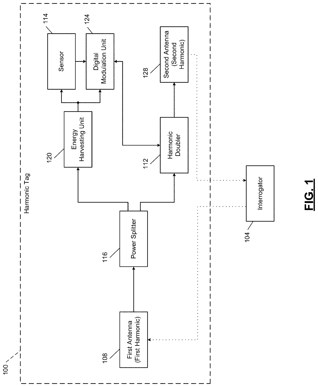
[0022]A passive harmonic radio frequency identification (RFID) tag integrated with a remote sensor is configured to transmit sensor data as well as identification information, for example, a tag identifier (ID). For remote sensing, automation, and control, multiple sensors are being integrated into one device. To distinguish between different sensors, there is a need to integrate the identifier (ID) / IP address in the sensors. RFID systems are popular for separating different tags by IP address. A further layer is added to the RFID system by making the RFID system capable of sensing. In the present disclosure, a radio frequency (RF) system is proposed, which can communicate the sensing data from a sensor along with the embedded tag ID by tailoring the harmonic generation of a fundamental frequency in the tag.

[0023]To improve signal to noise ratio (SNR) of a received signal due to en...


PUM


Abstract

A harmonic tag system includes a harmonic tag and a first antenna configured to receive a fundamental signal and transmit an identifier of the harmonic tag at a fundamental frequency. The harmonic tag system includes an energy harvesting unit configured to convert the fundamental signal into power. The power activates a sensor. The harmonic tag system also includes a harmonic doubler configured to generate a harmonic signal at a harmonic frequency based on (i) the fundamental signal and (ii) a sequence. The harmonic tag system further includes a digital modulation unit configured to selectively trigger an activation of the harmonic doubler. The harmonic doubler is triggered sequentially in an off state and an on state, and the digital modulation unit produces the sequence. The harmonic tag system also includes a second antenna configured to transmit data of the sensor at the harmonic frequency.

Description

CROSS-REFERENCE TO RELATED APPLICATIONS[0001]This application claims the benefit of U.S. Provisional Application 62 / 676,044, filed May 24, 2018. The entire disclosure of the above application is incorporated herein by reference.GOVERNMENT SUPPORT CLAUSE[0002]This invention was made with government support under DTPH56-15-H-CAP08 awarded by the U.S. Department of Transportation. The government has certain rights in this invention.FIELD[0003]The present disclosure relates to radio frequency identification (RFID) tags and, more specifically, transmitting data from RFID tags.BACKGROUND AND SUMMARY[0004]This section provides background information related to the present disclosure which is not necessarily prior art.[0005]Radio frequency identification (RFID) tags allow the identification of a product or object. RFID tags are typically small, unobtrusive, and lightweight, making them ideal for applications such as product handling, logistics, and security. Passive RFID tags operate by uti...

Claims


Application Information

Patent Timeline
IPC IPC(8): G06K7/10G06K19/073H04B5/00
CPCH04B5/0062G06K19/0724G06K7/10297G06K19/07309
Inventor CHAHAL, PREMJEET J.MONDAL, SAIKAT
Owner BOARD OF TRUSTEES OPERATING MICHIGAN STATE UNIV
Why Eureka
Try Eureka