Method and apparatus for managing wire rope slings

a technology of wire rope slings and slings, which is applied in the direction of web handling, transportation and packaging, rigid containers, etc., can solve the problems of difficult management, storage and transportation of sling groups, and difficulty in handling, so as to facilitate the lifting of the sling spool for transportation, facilitate the lifting of the sling spool, and facilitate the operation.

Inactive Publication Date: 2011-04-05
PAWS PUMPS
View PDF15 Cites 9 Cited by
  • Summary
  • Abstract
  • Description
  • Claims
  • Application Information

AI Technical Summary

Benefits of technology

[0013]The rotating sling storage plate or bin may be placed on a base plate or frame. The frame may have pad eyes for placement of slings to facilitate lifting the sling spool for transportation. The frame may also have a guide system or pathway such as spaces between framing members for receiving the tines of a forklift to further facilitate lifting the sling spool for transportation. The sling spool as contemplated and described is simple to operate and should have a compact design and “footprint” to minimize the space required for transporting and storing the sling spool as such space is limited on many work boats and drilling rigs.
[0014]The rotating sling spool allows the slings to be conveniently coiled around the sling retainers and stacked for stored on the rotating storage plate. This apparatus and method provides a convenient method to coil the slings, keeps them organized, readily transportable, and eliminates clutter on a drilling platform.

Problems solved by technology

The wire rope slings used in the oil and gas industry are heavy and cumbersome and difficult to manage, store and transport because of their length, weight, and flexible nature.
Storage and transportation of groups of slings can present a particular problem due to the space limitations typically associated with oil and gas drilling and production platforms.

Method used


Image

  • Method and apparatus for managing wire rope slings
  • Method and apparatus for managing wire rope slings
  • Method and apparatus for managing wire rope slings

Examples


Embodiment Construction

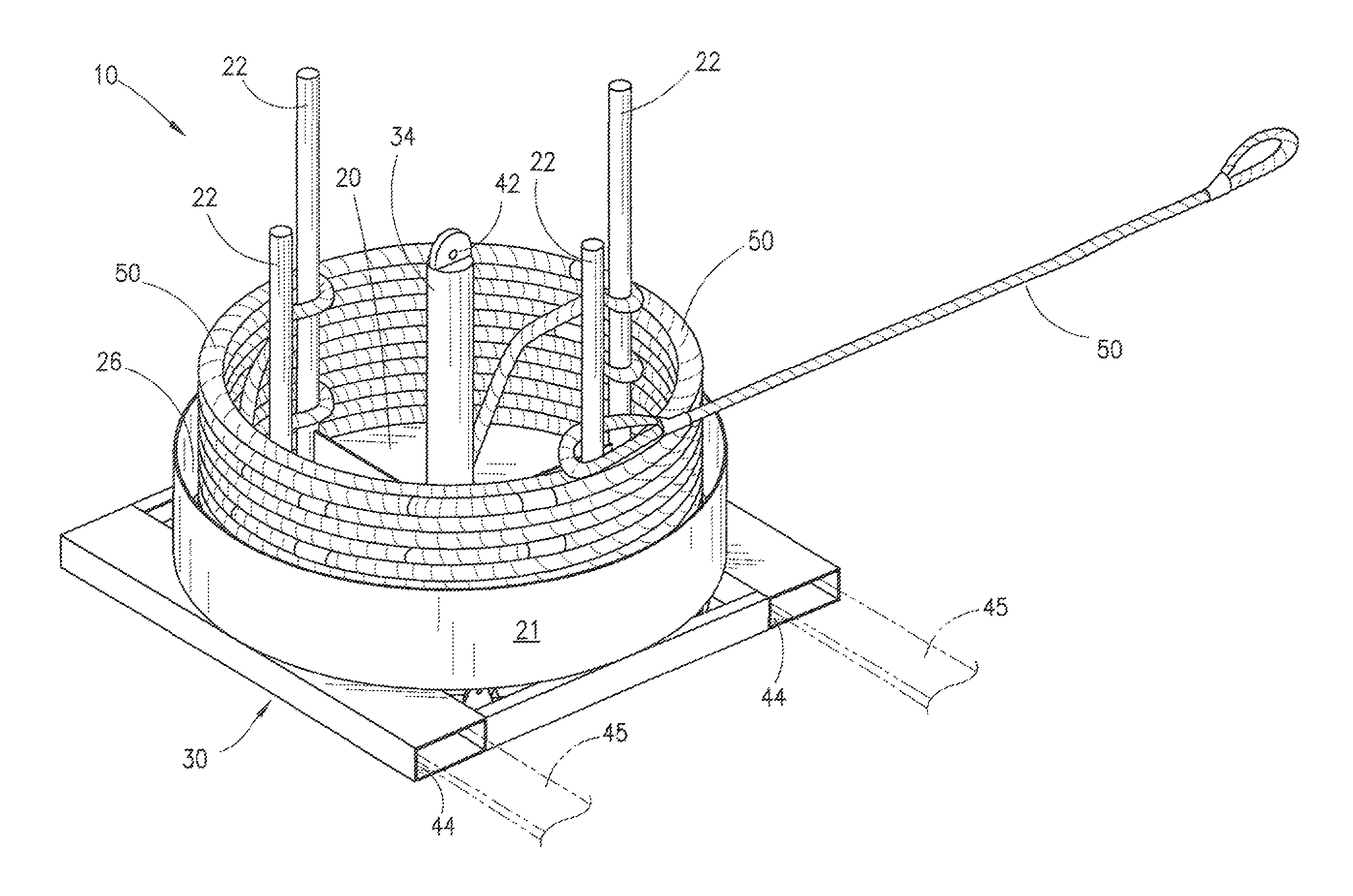
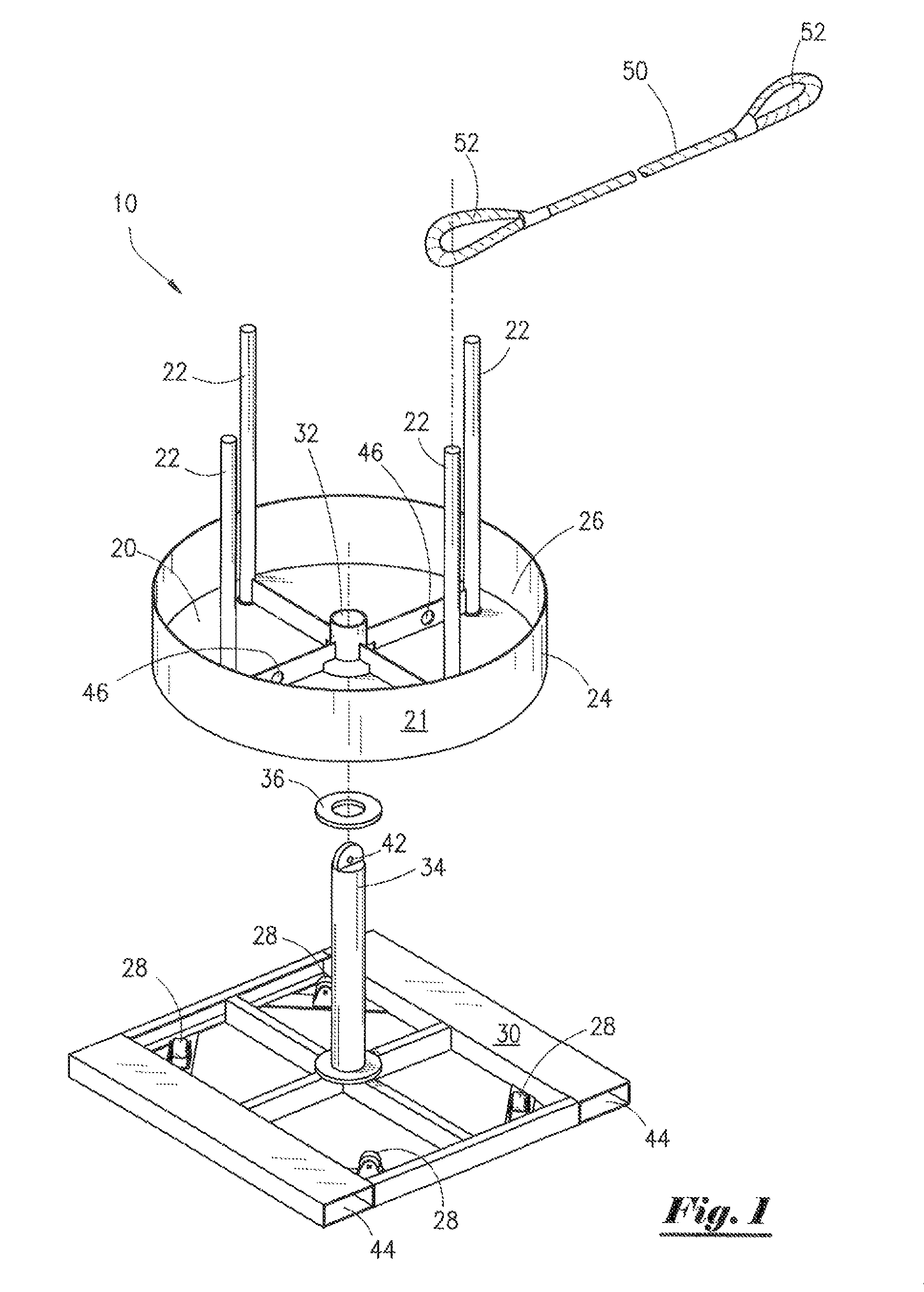
[0026]Referring now to the drawings and more particularly to FIG. 1, there is shown an exploded perspective view of sling spool apparatus (10) for managing, storing, and transporting conventional wire rope slings (50). It is contemplated that the wire rope slings (50) would be those comprised of a length of wire rope having a loop (52) at each end as shown though other sling configurations such as those with a loop (52) only at one end of the sling (50) or those with a clevis or hooked end at the ends of the sling (50) rather than a loop might also be utilized with the apparatus (10).

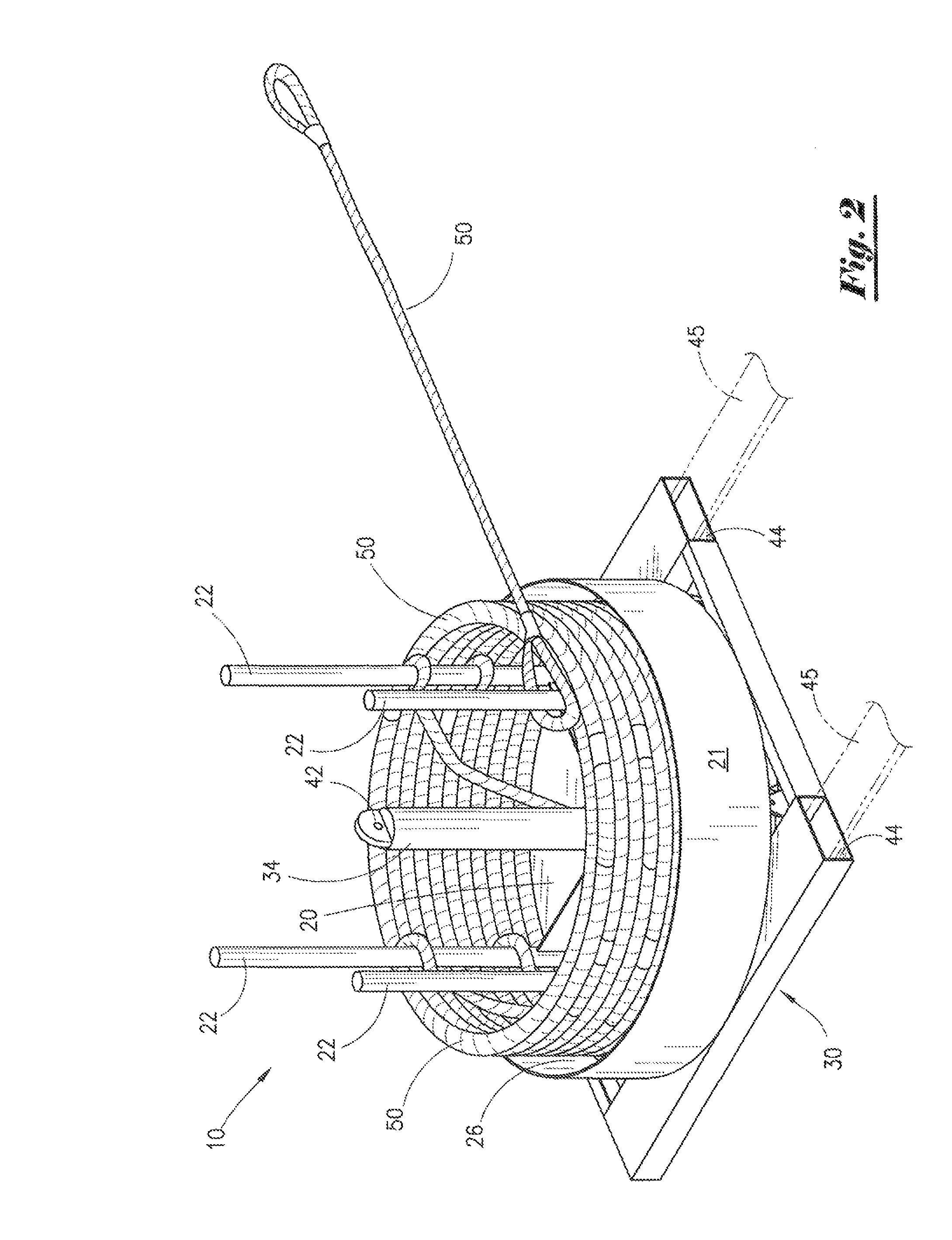
[0027]In the embodiment shown in FIG. 1, again in FIG. 2, and in cross-section in FIG. 7, a substantially horizontally orientated sling storage plate (20) is rotatably mounted upon a substantially horizontally orientated base frame (30) to form a bin assembly (21). As can be seen in FIG. 2, FIG. 3, and FIG. 4, the sling storage plate (20) has at least one and preferably two pair of substantially vertica...


PUM


Abstract

An apparatus for the storing and management of a plurality of wire rope slings is presented, such slings being those typically comprised of a length of wire rope having at least one end loop. The apparatus has a base frame upon which is rotatably mounted a sling storage bin. The storage bin has a plurality of arm members that extend from the storage bin for engaging and holding an end loop of a selected wire rope sling. Rotation of the storage bin causes the selected wire rope sling to be coiled around said projecting arms within the storage bin. The apparatus may be provided with pad eyes and forklift tine guides to facilitate its transportation.

Description

FIELD OF INVENTION[0001]This invention generally relates to the field of wire rope sling storage and management. More particularly, it provides an improved method and apparatus for managing and transporting wire rope slings used in the shipping and oil and gas industries for hoisting, lifting, and transporting goods and materials.BACKGROUND OF INVENTION[0002]A typical metal wire rope lifting sling is comprised of a length of wire rope having a loop at each end formed by inserting or fitting the rope ends into a sleeve which is then swaged to bind the rope ends into a loop. These wire rope slings are commonly utilized as rigging for lifting and securing heavy loads. In the oil and gas industry, such slings are typically utilized for transporting, hoisting, and lifting shipping containers, pipe, materials, and equipment that are used in the drilling and production of oil and gas to and from well locations.[0003]In the oil and gas industry wire rope slings are typically leased or rente...

Claims


Application Information

Patent Timeline
Patent Type & Authority Patents(United States)
IPC IPC(8): B65H75/00
CPCB65H75/28B65H75/403B65H2701/35
Inventor DAVIS, EDWARD W.LEBLANC, THOMAS E.HIDALGO, WILLIAM H.
Owner PAWS PUMPS
Why Eureka
Try Eureka