Method and apparatus for measuring a distance

a technology of distance measurement and distance, applied in the direction of mechanical diameter measurement, survey, borehole/well accessories, etc., can solve the problems of limited accuracy of data, difficult maintenance, and often significant errors in the process of measuring these characteristics

Inactive Publication Date: 2005-02-01
HALLIBURTON ENERGY SERVICES INC
View PDF16 Cites 25 Cited by
  • Summary
  • Abstract
  • Description
  • Claims
  • Application Information

AI Technical Summary

Benefits of technology

The distance measurement device measures the distance “R” from the surface of the housing engaged with a first reference point to the flexible member curve apex in the radial direction, with the apex being axially offset from the housing. The measurement device has a default position where the flexible member apex extends to a maximum distance “R”. Placing the housing contact surface against the first reference point and the flexible member apex against a second reference point with a radial distance less than the maximum distance “R” constrains the flexible member and adjusts the position of the flexible member apex. Changing the distance “R” and thus the radial position of the apex slides the flexible member housing end within the housing slide track. There is a unique correlation between the location of the flexible member housing end and the radial position of the flexible member apex. Using the information gathered by the sensors and the known dimensions and properties of the distance measurement device, the distance measurement device can thus measure the radial distance “R” from the contact surface of the housing to the flexible member apex, and thus the distance between the two reference points. Because the device has no moving parts other than the flexible member, it is very reliable, inexpensive, and easy to maintain. Alternatively, the base may be free to move axially relative to the housing.

Problems solved by technology

However, the processes often employed to measure these characteristics are subject to significant errors unless information on the borehole size and configuration is also taken into account in their determination.
However, this technique has practical limitations because of the mechanical instability of the caliper arms.
However, the techniques proposed with acoustic calipers entail measurements employing standoff and travel time calculations, resulting in data of limited accuracy.
Sound wave reflections in soft formations may also be too weak to be accurately detected, leading to loss of signals.

Method used


Image

  • Method and apparatus for measuring a distance
  • Method and apparatus for measuring a distance
  • Method and apparatus for measuring a distance

Examples


embodiment 210

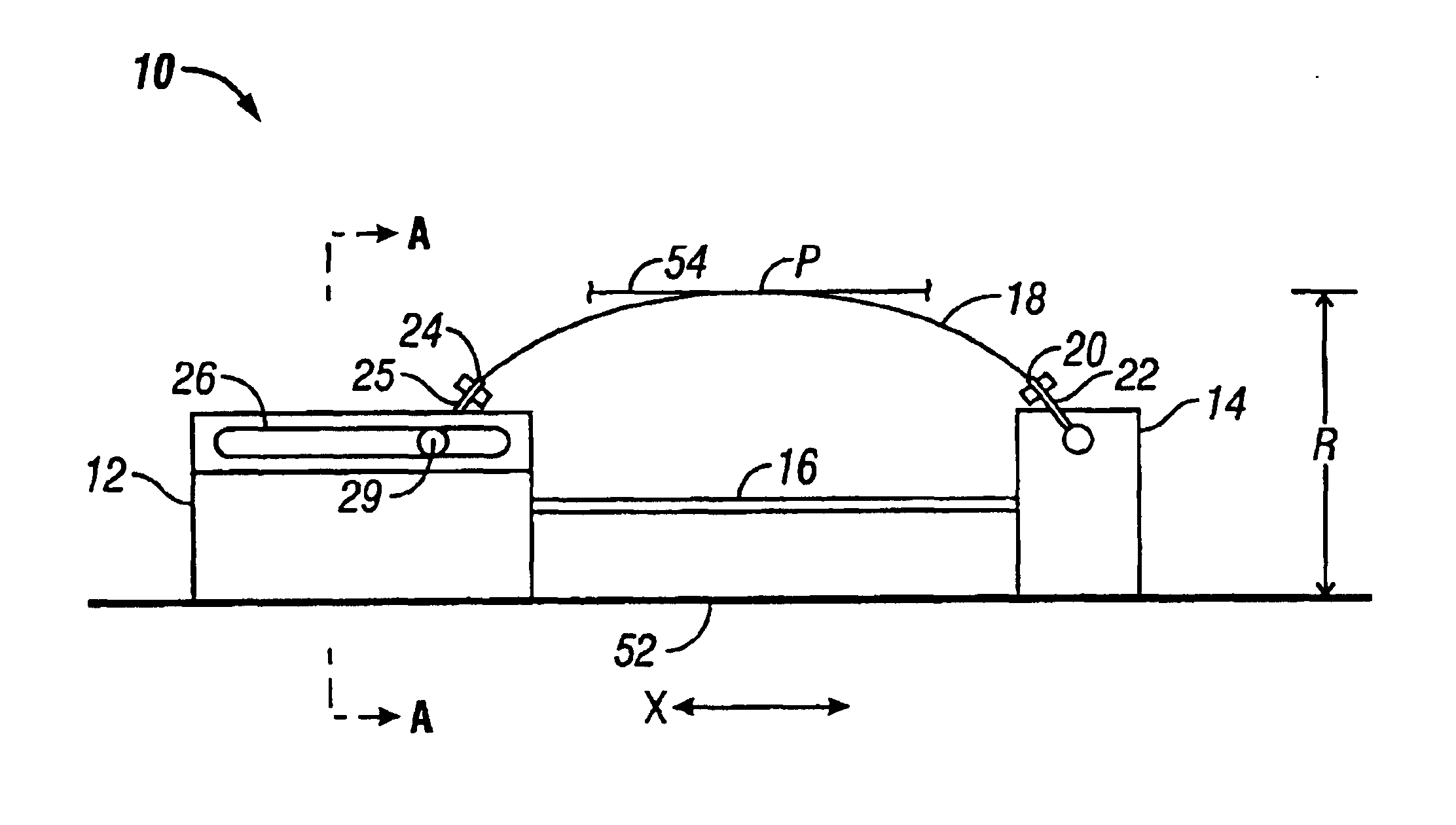
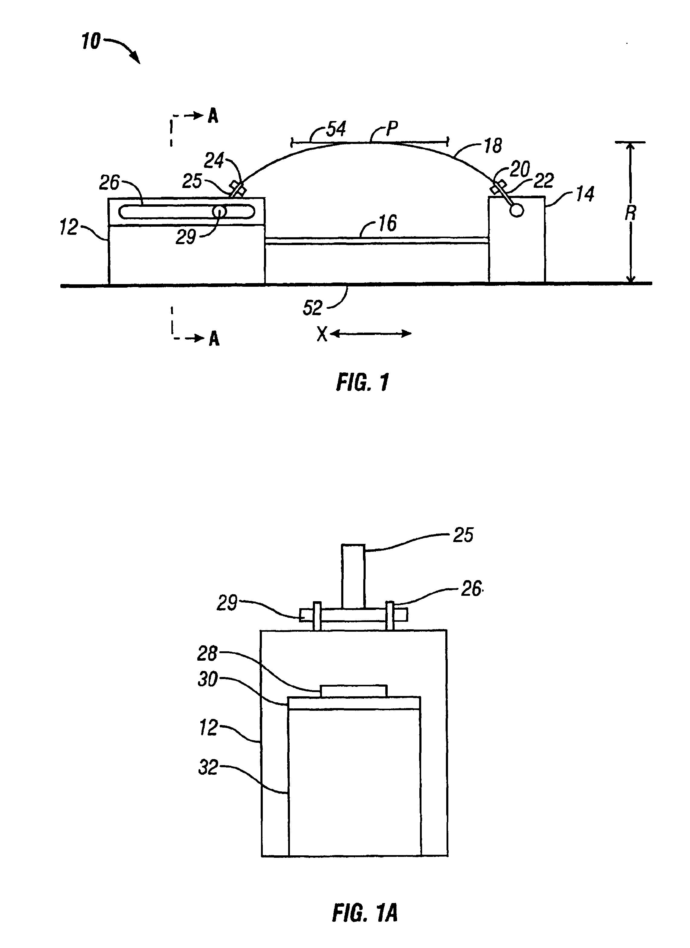
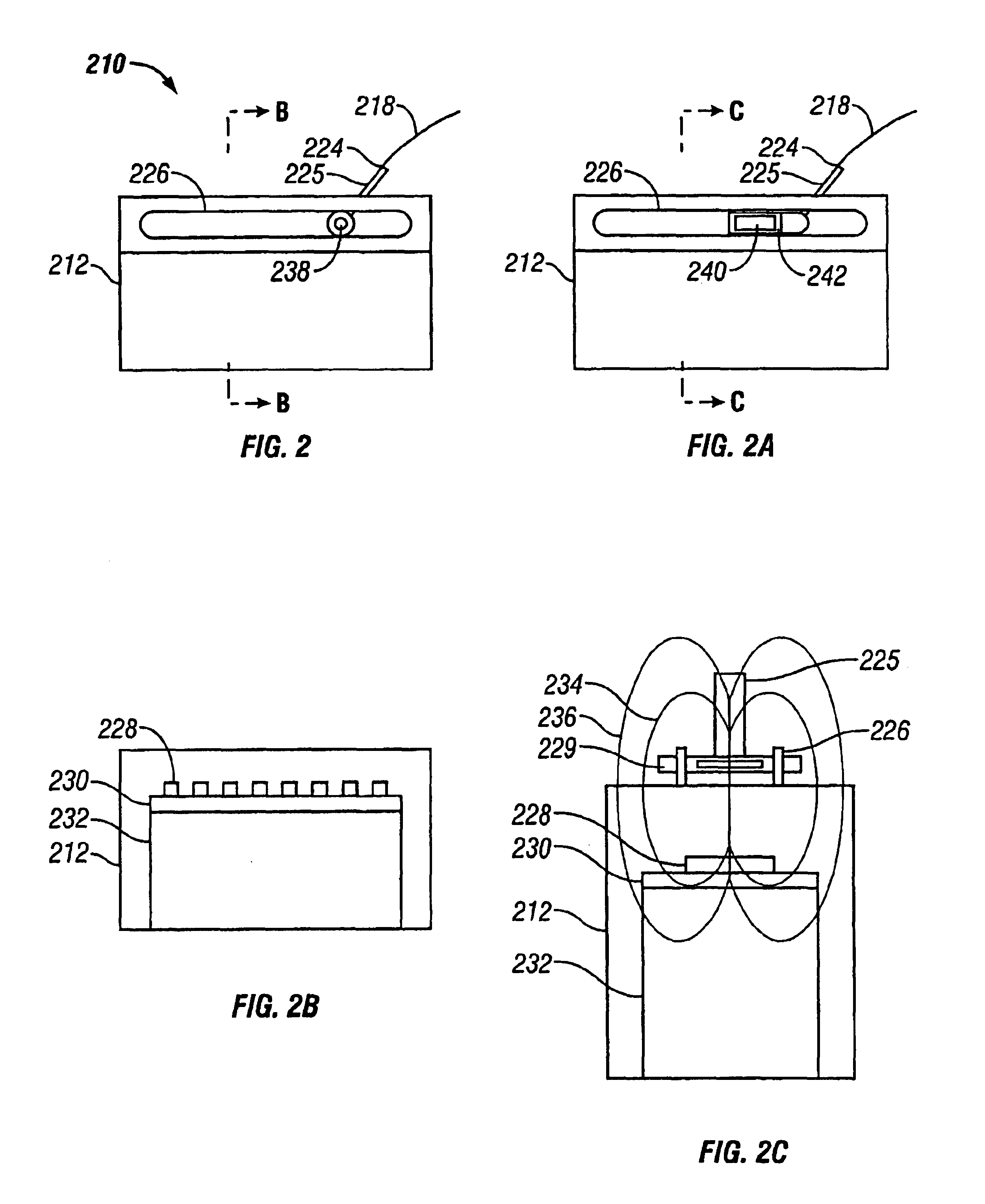
FIGS. 2 and 2A-2C show another embodiment 210 of the distance measurement device. For simplicity, FIGS. 2 and 2A-2C only show the housing 212 portion of the distance measurement device 210. The remainder of the distance measurement device 210 is similar to the distance measurement device 10 described above. With the measurement device 210, however, the flexible member housing end 224 comprises a permanent magnet 238 included in the bracket 225 with the North-South field oriented radially. The magnet 238 produces a magnetic field inside the housing 212 indicated by flux lines 234, 236 shown in FIG. 2C. The magnetic field moves as the flexible member housing end 224 moves within the housing slide track 226, thus indicating a change in the distance “R”. An array of sensors 228 located inside the housing 212 detect the magnetic field of the magnet 238. By way of example only, the sensors 228 may be Hall-effect sensors. However, any suitable sensors for detecting the magnetic field may b...

embodiment 310

FIGS. 3 and 3A show another embodiment 310 of the distance measurement device. The distance measurement device 310 comprises a housing 312, a base 314, and a first flexible member 318 and operates in a similar manner to the distance measurement device 10. In addition to the first flexible member 318, the distance measurement device 310 also comprises a second flexible member 344 opposite the first flexible member 318. The second flexible member 344 is similar to flexible member 318, comprising a housing end 350 with bracket 351 and a base end 346 with bracket 348. The flexible member housing end 350 slides in a second slide track 327. The distance measurement device 310 may also comprise more than two flexible members, such as three or four flexible members, with the flexible members being azimuthally spaced around the housing 312. Thus, instead of measuring one radial distance “R”, the distance measurement device 310 also measures at least one additional distance “R2” to determine ...

embodiment 410

FIGS. 4 and 4A show another alternative embodiment 410 of the distance measurement device installed on a downhole tool 456, such as a downhole logging tool, and placed in a borehole 458. The distance measurement device 410 measures the diameter “D” of the borehole 458. The housing 412 and the base 414 may be integrated with or attached onto the downhole tool 456. When attached to the downhole tool 456 and placed downhole in the borehole 458, the flexible member 418 engages the side of the borehole wall 454. Additionally, opposite the flexible member 418, the downhole tool 456 engages the opposite side of the borehole wall 452. The flexible member 418 biases the opposite side of the downhole tool 456 against the side 452 of the borehole wall. The housing 412 and the base 414 are configured for attachment onto the downhole tool 456. Although, as shown in FIG. 4A, the housing 412 and the base 414 are generally “arc-shaped”, the housing 412 and the base 414 may be any configuration such...


PUM


Abstract

A distance measurement device and method for measuring a distance between two reference points comprising a housing, a base, and a flexible member curving therebetween. The flexible member housing end is allowed to slide in a slide track in the housing. The housing also comprises sensors that detect the position of the flexible member housing end relative to the housing. The distance measurement device measures the distance between the two reference points by engaging the first reference point with the housing and engaging the second reference point with the flexible member apex. As the distance from the housing to the flexible member apex changes, the flexible member housing end slides in the housing slide track. There is a unique correlation between the location of the flexible member housing end and the distance to flexible member apex, and thus the second reference point. Using the information gathered by the sensors and the known dimensions of the housing, the distance measurement device thus measures the distance from the first reference point to the second reference point.

Description

STATEMENT REGARDING FEDERALLY SPONSORED RESEARCH OR DEVELOPMENTNot Applicable.BACKGROUND OF THE INVENTION1. Field of the InventionThe present invention relates to distance measuring devices.2. Description of the Related ArtIt is often necessary to measure a distance between two measurement points such as from a first surface to another surface. For example, in order to improve oil and gas drilling and production operations, it is necessary to gather as much information as possible on the properties of the underground earth formation as well as the environment in which drilling takes place. Such properties include characteristics of the earth formations traversed by a well borehole, in addition to data on the size and configuration of the borehole itself. Among the characteristics of the earth formation measured are the resistivity, the density, and the porosity of the formation. However, the processes often employed to measure these characteristics are subject to significant errors ...

Claims


Application Information

Patent Timeline
Patent Type & Authority Patents(United States)
IPC IPC(8): E21B47/08E21B47/00
CPCE21B47/08
Inventor MOAKE, GORDON L.RINGGENBERG, PAUL DAVID
Owner HALLIBURTON ENERGY SERVICES INC
Why Eureka
Try Eureka