Blow box for controlling the web run

a web run and blow box technology, applied in the field of blow box, can solve the problems of increasing the required blowing effect, increasing the energy cost, and increasing the energy cost, and achieve the effects of facilitating the adjustment of the distance of the blocking member, and reducing the pressure in the space behind the blocking member

Inactive Publication Date: 2005-02-01
VALMET TECH INC
View PDF10 Cites 10 Cited by
  • Summary
  • Abstract
  • Description
  • Claims
  • Application Information

AI Technical Summary

Benefits of technology

The blocking member used in the solution according to the invention moves substantially more delicately than a blocking member projected by a spring towards the wire. By controlling the pressure acting on the blocking member's back surface directed away from the wire or on the blocking member's blocking surface it is easy to adjust the blocking member's distance from the wire, i.e. the gap between the blow box and the wire. The blocking member's back surface directed away from the wire can be arranged to border to a separate pressurised space, or to a pressurised space which can be controlled in part independently. By controlling the pressure of this space it is possible to push the blocking member towards the wire with a desired pressure. Already a very small change in the pressure makes the blocking member to move in the desired direction. Thus a blocking member, which can be freely rotated around the hinge's articulation point, can be easily pushed towards the blow box due to a very small “paper lump” or some other approach of the wire, without damage to the wire or to the actual blocking member.
Even a small pressure change on either side of the blocking member causes the blocking member to move towards the wire or away from the wire. The air jets, which are blown along the blocking member's surface and which eject air from die negative pressure region, will cause a negative pressure between the blocking member and the wire, whereby this negative pressure pushes the blocking member towards the wire and prevents air leaks from entering the negative pressure region. The blocking member can be prevented from extending too close to the wire with the aid of a mechanical limiter, against which the blocking member hits when it rotates to the allowed extreme position, and which thus prevents the blocking member from rotating past this extreme position. Thus a blow box according to the invention can be arranged very close to the web.
When using a blow box according to the invention it is possible to advantageously arrange both blocking members and blow nozzles both at the beginning and at the end of the negative pressure region, whereby the nozzles blow / eject air out from the negative pressure region along the blocking member's surface. Together the ejecting blows and the blocking members prevent effectively air from escaping from the outside of the negative pressure region into the negative pressure region. The nozzles, which can be fixedly joined to the blow box can be arranged at a safe distance from the web.
In addition the blocking member and the blow nozzle at the corresponding point are advantageously shaped congruently, so that the blocking member's blocking surface passes along the outer surface of the nozzle when the blocking member is rotating and leaves a gap of a desired size between the nozzle and the blocking surface. The blocking surface and the nozzle are advantageously shaped so that the gap between them grows as the blocking member is pushed away from the wire, whereby more air than in the normal state is allowed to flow out from behind the blocking member, in other words from the space between the blocking member's back surface and the blow box. Then the pressure in the space behind the blocking member will decrease, and the blocking member can be pushed more easily than before away from the wire. In this manner the blocking member can be rapidly pushed away from the wire, for instance when a “paper lump” pushes the wire towards the blow box.
When desired, it is also possible to arrange members in the blow box in order to suck air away from the negative pressure region. In this way the negative pressure can be intensified, even to a level above 5 kpa. In addition, when required it is possible to maintain a lower negative pressure than this intensified negative pressure, such as a negative pressure of 0.1 to 0.4 kPa, in the other parts of the pocket, in other words outside the intensified negative pressure region.
In a blow box according to the invention a blocking member arranged at the beginning of the negative pressure region can at its first end, as seen in the running direction of the web, be connected to the blow box e.g. with a swing joint, which allows a frictionless or almost frictionless movement of the blocking member around the articulation point of the swing joint. A counter weight can be connected to the first end of the blocking member in order to keep the blocking member in balance at the desired distance from the web during a normal run. This facilitates keeping the gap between the web and the blocking member at a desired size. Thanks to the counter weight the blocking member is at a particularly mobile state, in other words it can be turned away from the wire or towards the wire in a sensitive manner.

Problems solved by technology

However, the intensifying of the negative pressure level from the present, i.e. the maintaining of an even higher negative pressure with the aid of blowers, substantially increases the required blowing effect, in other words the energy costs.
The higher the aimed negative pressure level, the larger are also the air leaks and their impacts on the energy costs.
It is not possible to completely seal the negative pressure region from the surrounding space in order to reduce the leaks.
Blocking members, blow nozzles or other structures of a blow box arranged too close to the wire can easily damage the wire, and they can themselves be easily damaged when the wire touches them.
However, springs are generally relatively stiff, and they are not sufficiently resilient in order to be able to adapt to all situations sufficiently rapidly.
In addition, the spring force cannot be adjusted to different requirements.

Method used


Image

  • Blow box for controlling the web run
  • Blow box for controlling the web run
  • Blow box for controlling the web run

Examples


Embodiment Construction

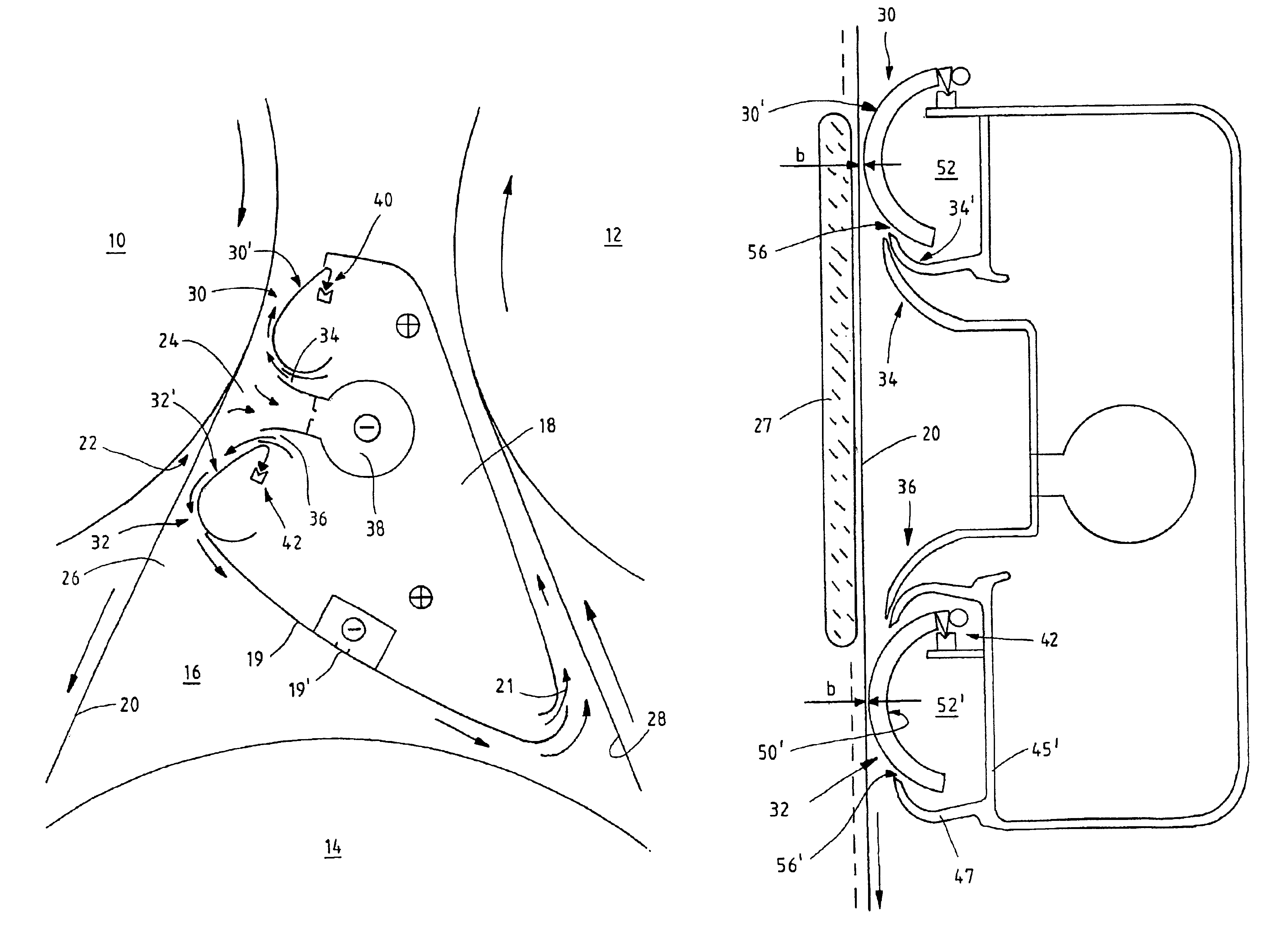
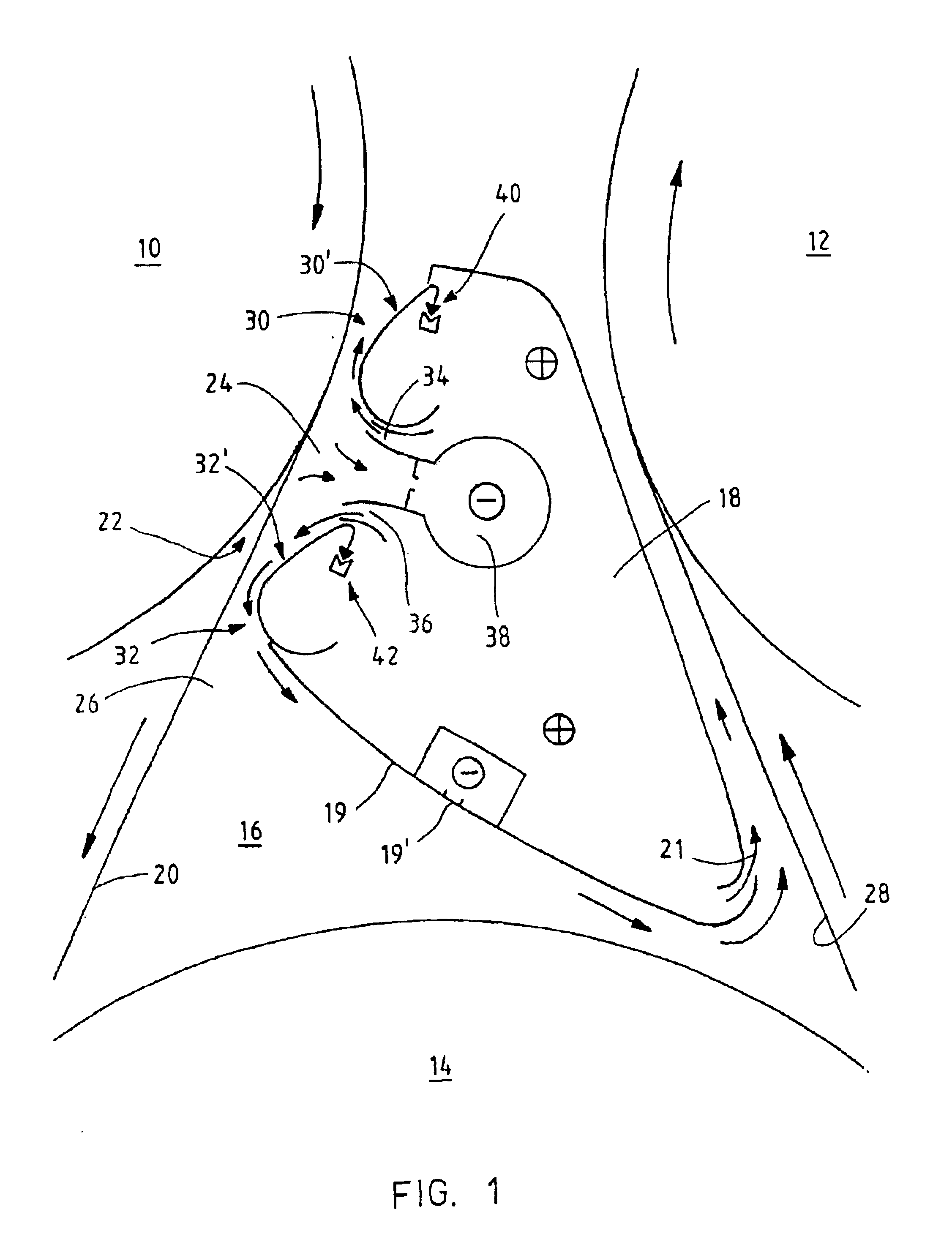
FIG. 1 shows a cross section of the drying section of a paper machine provided with a single wire run, a pocket 16 formed between its two drying cylinders 10, 12 and a suction roll 14, where a blow box 18 according to the invention is arranged. The blow box 18 is arranged between the first drying cylinder 10 and the second drying cylinder 12 in the running direction of the wire 20, which supports the web.

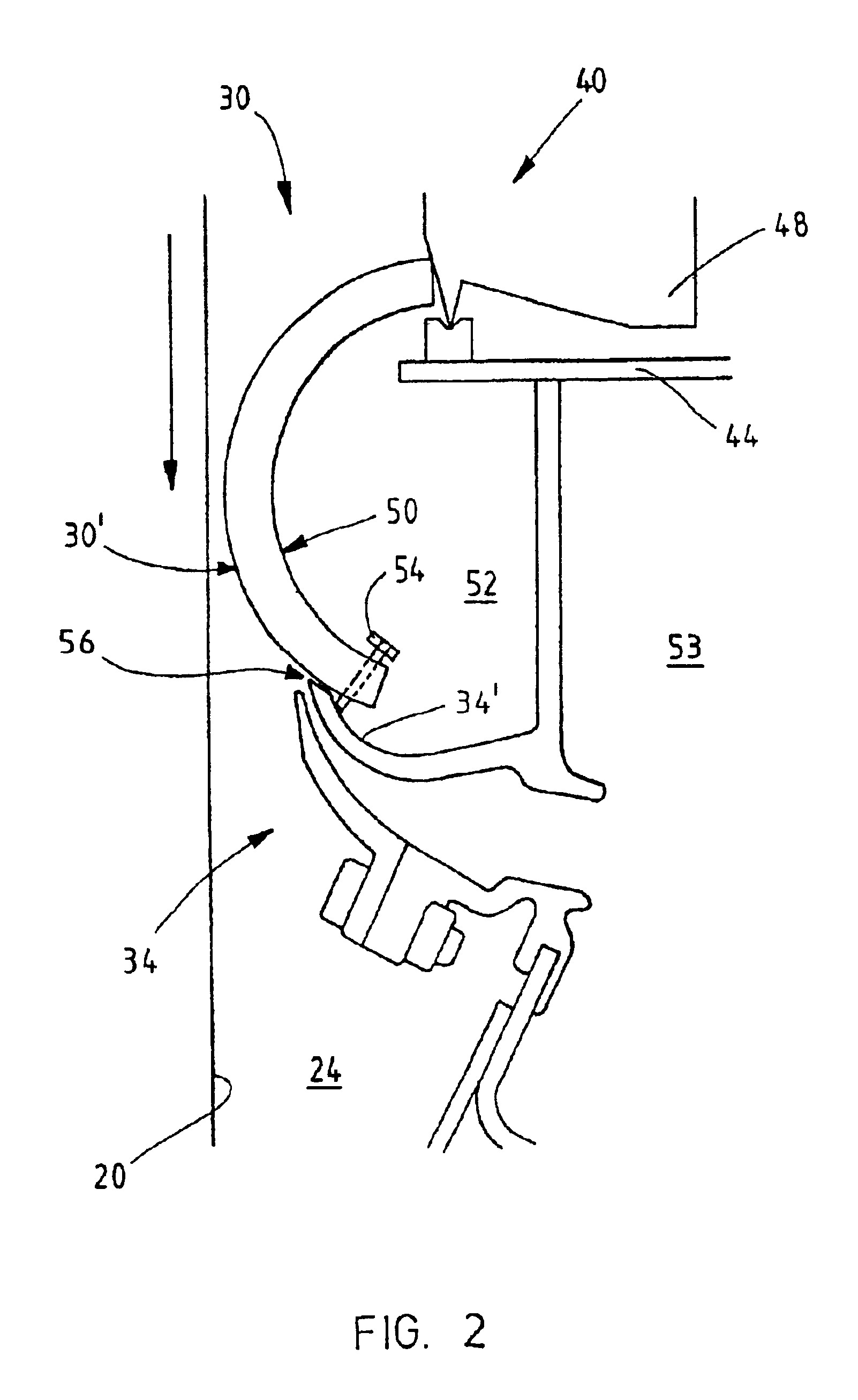
The blow box 18 is arranged to cover the wire run 20 at a point where the wire is released from the first drying cylinder 10, in other words at the opening nip 22 between the wire and the drying cylinder. The blow box creates in this point a intensified negative pressure region, in the space 24 between the wire 20 and the blow box 18, whereby this space is sealed from the rest of the space of the pocket 16.

In the solution presented in FIG. 1 the blow box does not cover the wire run 20 on the later part 26 after the opening nip between the first drying cylinder 10 and the suction rol...


PUM


Abstract

A blow box (18) for supporting the web run in a paper machine or the like, which blow box comprises members for maintaining a negative pressure at least in one negative pressure region (24) between the wire (20) and the blow box. The members comprise a blocking member (30, 32), which is arranged, regarding the wire's running direction, at the beginning and/or at the end of said negative pressure region, which extends across the wire and projects towards the wire, and which is movable in relation to the blow box, and blowing members (34, 36), with which air is ejected with blows between said blocking member and the wire from said negative pressure region and/or with which air is prevented from entering this negative pressure region. The blocking member is connected to the blow box by a hinge member (40, 42), which allows the blocking member to rotate around the articulation point of the hinge member due to the pressure difference between the pressure acting on the blocking member's blocking surface (30′, 32′) directed towards the wire and the pressure acting on the blocking member's back surface (50, 50′) directed away from the wire.

Description

BACKGROUND OF THE INVENTIONThe present invention relates to a blow box for controlling or supporting the web run in a paper machine, particularly in the drying section of a paper machine, or in other corresponding devices, such as in a board machine, in a finishing machine and in coating machines.The web run needs control or support, for instance during running in the area of the pockets formed between the drying cylinders in the drying section of a paper machine, particularly in such locations where the web needs to be released in a controlled manner from a drying cylinder and to run freely together with the wire to a turning roll, suction roll or the like.In order to support the web at the pockets of the drying section it is known to use blow boxes, which eject air away from desired regions in order to create a negative pressure in these regions. Thus the negative pressure created by the blow boxes can be used to support the release of the web from a drying cylinder and to support...

Claims


Application Information

Patent Timeline
Patent Type & Authority Patents(United States)
IPC IPC(8): D21F5/00D21G9/00D21F5/04
CPCD21G9/0063D21F5/042
Inventor LEIMU, JUHA
Owner VALMET TECH INC
Why Eureka
Try Eureka