
Shock force indicating device

a technology of shock force and indicating device, which is applied in the direction of instruments, force/torque/work measurement apparatus, packaging, etc., can solve the problems of device not being able to visually identify the extent of device not being able to measure the shock or force exerted on the package or product, device not being able to visually identify the shock or force exerted on an article,

Active Publication Date: 2005-02-01
GATEWAY
View PDF17 Cites 71 Cited by
  • Summary
  • Abstract
  • Description
  • Claims
  • Application Information

AI Technical Summary

Benefits of technology

In one preferred embodiment, the base member and top member provide a compressing force to the bearing such that the bearing is held in place until the device is subjected to a shock force exceeding a predetermined threshold. The bearing has a starting point, in one embodiment, which is substantially centered in the plane of the base member within the device between the base member and the top member. In another embodiment, the bearing is disposed within an indentation in the base member. When the device is subjected to a shock force greater than a predetermined threshold, the bearing will travel a particular distance from its starting position and will visually identify the extent of the shock force.
To visually display the extent of the shock force, there is a pressure sensitive material disposed on the base member. Movement of the bearing over the pressure sensitive material provides a visually identifiable path on the pressure sensitive material which traces the movement of the bearing when the bearing moves in response to a shock force to the device. The pressure sensitive material may be pressure sensitive paper, such as carbon paper, but is optionally any other suitable material. The base member has indicating marks which represent a scale with which to measure a component of a force applied to the device. The indicating marks may consist of substantially concentric circles. The top member is transparent for easy viewing of the indicating marks.

Problems solved by technology

These devices, however, do not visually show the extent of shock or force exerted on an article, such as a package or product, during shipping or handling of the article.
However, the device is incapable of measuring the extent of shock to the package or product.
While the device may indicate that a product has received a shock force over a predetermined threshold, the device is incapable of visually identifying the extent of shock to an article.
While the device may also indicate that a product has received a shock force over a predetermined threshold, the device is incapable of measuring the extent of shock to the package or product.
However, the device does not allow someone to visually confirm to what extent a package or product has been subjected to a force or shock.
Other conventional shock force indicating devices are capable of informing an individual of the extent of shock, however, they require one to download such information from the device and therefore, the extent of shock information is not readily ascertainable upon visual inspection.
Therefore, an individual receiving a package at his home could not visually inspect the package and immediately make a decision to refuse or accept the package based on the device.
Such information is not available upon visual inspection and the process for obtaining such data is very time consuming and often impractical for typical receiving situations.
The device is also incapable of displaying data as to the extent of shock to an article by simple visual inspection and requires time-consuming manipulation of the device.

Method used


Image

  • Shock force indicating device
  • Shock force indicating device
  • Shock force indicating device

Examples


Embodiment Construction

While this invention is susceptible of embodiments in many different forms, there is shown in the drawings and will herein be described in detail preferred embodiments of the invention with the understanding that the present disclosure is to be considered as an exemplification of the principles of the invention and is not intended to limit the broad aspect of the invention to the embodiments illustrated.

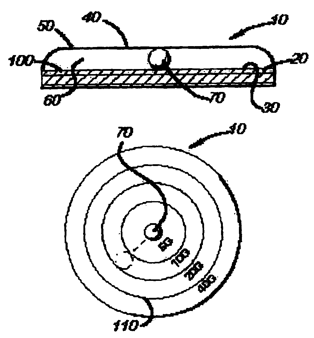
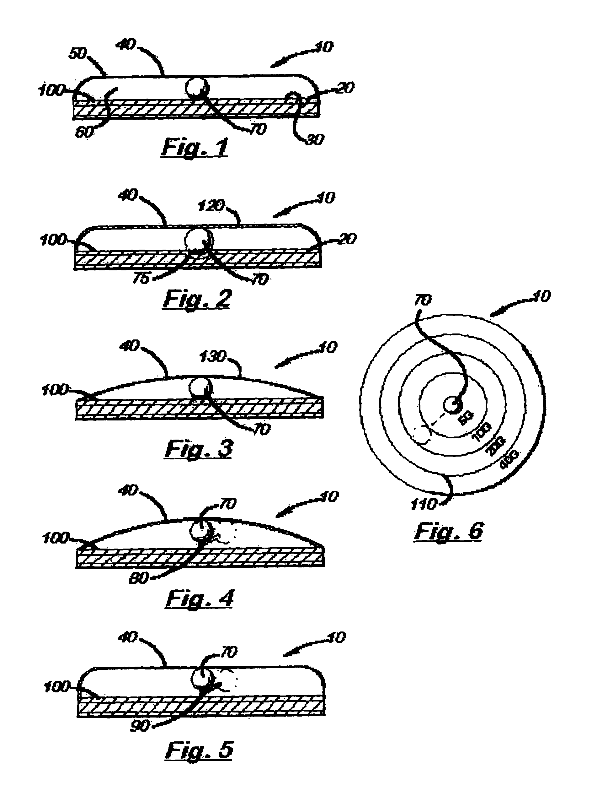
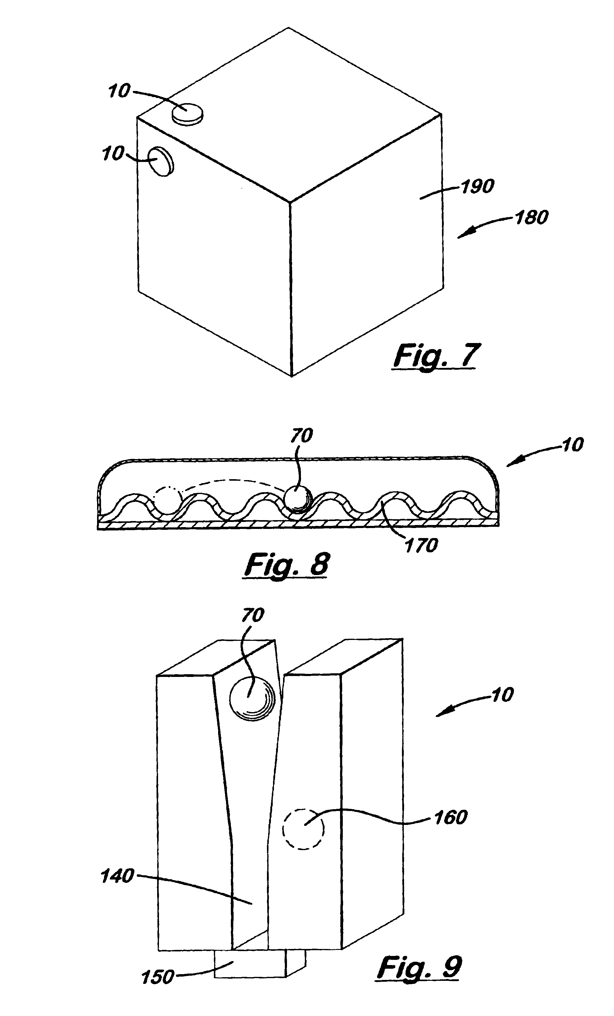
The present invention is a shock force indicating device 10 for measuring and immediately displaying the extent of a shock force on an article, such as a package or product, during shipping or handling of the article. The device 10 is optionally applied to the outside of a package via an adhesive backing or other suitable means. Alternatively, the device 10 is optionally placed inside packaging with the product or is adhered to the product itself. The device 10 improves the handling of shipped products or of any other product requiring careful handling because the device 10 provides ...


PUM


Abstract

A shock force indicating device for measuring and visually displaying the extent of a shock force received by an article during handling of the article is disclosed. The device has a cavity formed between a base member and a top member having a raised portion. A bearing is disposed within the cavity. In a preferred embodiment, the top member and the base member provide a compressive force to the bearing such that the bearing is held in place until the device is subjected to a shock force greater than a predetermined threshold. The base member has a pressure sensitive material which provides a visually identifiable path which traces the movement of the bearing when the bearing moves in response to a shock force to the device. The base member may have indicating marks for representing a scale with which to measure a component of a force to the device. The top member is transparent for easy viewing of the indicating marks. The base member may have an adhesive on a bottom portion for attaching the device directly to a package or other article.

Description

FIELD OF THE INVENTIONThe present invention relates to a shock force indicating device, and more specifically to a shock force indicating device which measures and visually displays the extent of a shock force to an article.BACKGROUND OF THE INVENTIONSeveral conventional shock force indicating devices are known and utilized in the shipping and retail industries. These devices, however, do not visually show the extent of shock or force exerted on an article, such as a package or product, during shipping or handling of the article. Many such devices merely inform the user that the package or product has received a shock force that is over a specific, predetermined threshold. For example, one such device has a tiny liquid-filled glass tube housed in a self-adhesive label. If the device receives a shock beyond a predetermined threshold, the liquid in the tube changes from clear to bright red. However, the device is incapable of measuring the extent of shock to the package or product.Add...

Claims


Application Information

Patent Timeline
IPC IPC(8): G01L5/00B65D79/02
CPCG01L5/0052B65D79/02
Inventor ELSASSER, DAN WILLIAMMEYER, CORWYN R.
Owner GATEWAY
Features
  • Generate Ideas
  • Intellectual Property
  • Life Sciences
  • Materials
  • Tech Scout
  • Unparalleled Data Quality
  • Higher Quality Content
  • 60% Fewer Hallucinations
Learn More