Flexible tube

a flexible tube technology, applied in the direction of adjustable joints, mechanical devices, machines/engines, etc., can solve problems such as noise, and achieve the effect of restricting the vibration amplitud

Inactive Publication Date: 2005-02-01
CALSONIC KANSEI CORP
View PDF15 Cites 48 Cited by
  • Summary
  • Abstract
  • Description
  • Claims
  • Application Information

AI Technical Summary

Benefits of technology

According to a first aspect of the invention, there is provided a flexible tube including a bellows tube, an interlock pipe, and a restriction member. The bellows tube has a bellow portion and straight portions, which is formed both ends thereof. The interlock pipe in which a plurality of annular plate members or spirally wound band plates are flexibly coupled at side edges thereof to one another through an interlock mechanism, is disposed inside the bellows tube to have a common axis. The restriction member is disposed on the bellow portion and serves as a fulcrum to restrict vibration amplitude of the interlock pipe when the interlock pipe is vibrated. Inner diameter of the straight portions tube is larger than that of first small-diameter parts of the bellow portion. Inner peripheral surfaces of the straight portions are fixed to an outer surface of the interlock pipe.

Problems solved by technology

As a result, the outer peripheral face of the interlock pipe 4 and the bellows portion 9c contact with each other, thereby causing troubles such as noises.

Method used


Image

  • Flexible tube
  • Flexible tube
  • Flexible tube

Examples


second embodiment

FIG. 3 shows a

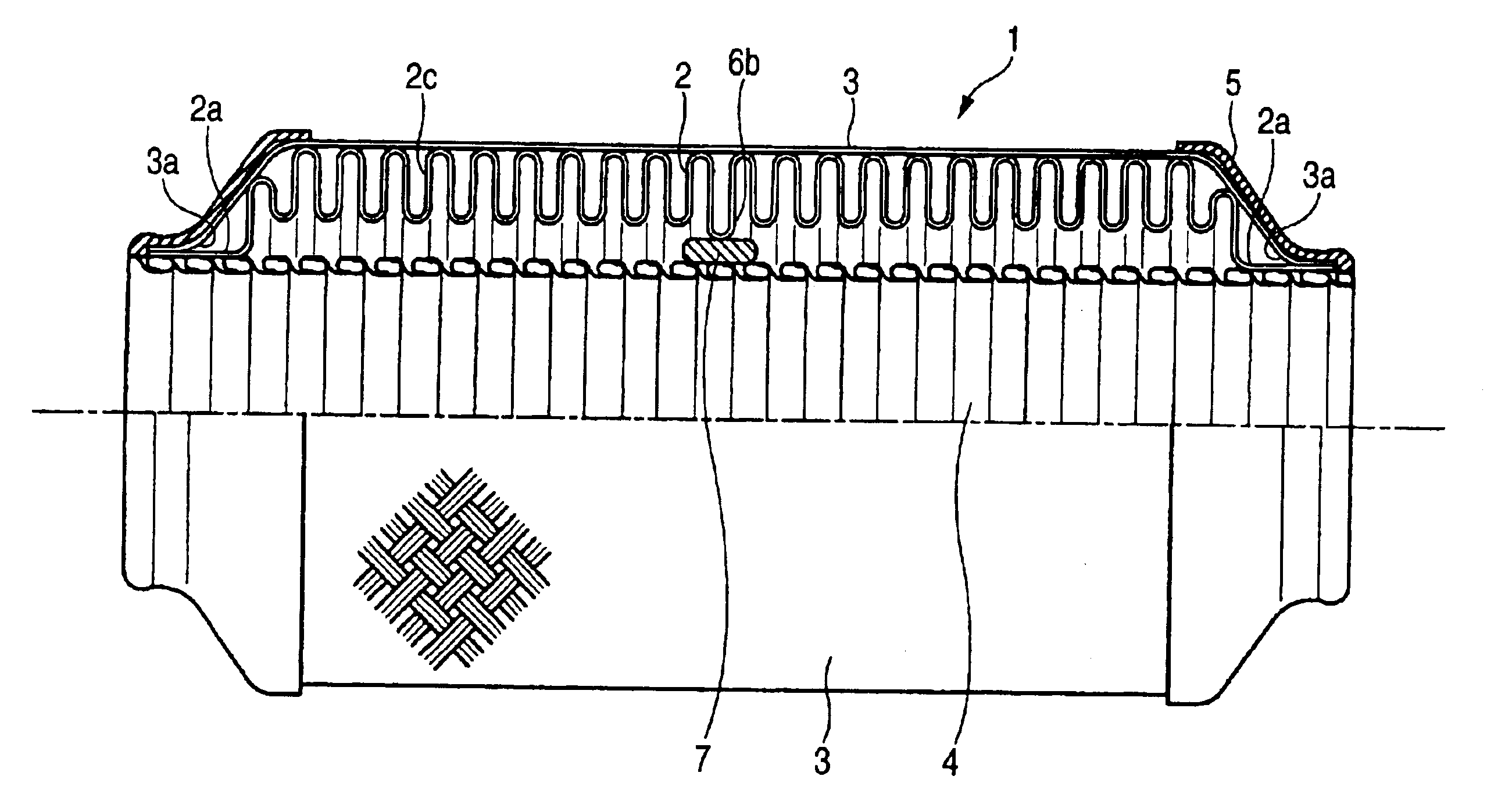
A small diameter part which is part of restriction member, 6b in the vicinity of a center portion of the bellows portion 2c of the bellows tube 2 in an axial direction, has a smaller diameter than the usual small-diameter parts. However, the small-diameter part 6b does not butt against the interlock pipe 4. A restriction buffer member 7 is attached in a gap between an inner peripheral end of the small-diameter part 6b and the interlock pipe 4 so that the small-diameter part 6b restricts the swing of the interlock pipe 4 through the restriction buffer member 7. The restriction buffer member 7 is attached to a place in the vicinity of a center of the interlock pipe 4 corresponding to the small-diameter part 6b, by spot welding or the like.

In the embodiment, the small-diameter part 6b and the buffer member 7 attached to the interlock pipe 4 may constitute the restricting member in the invention.

The small-diameter part 6b is set to have a smaller diameter so that it does n...

third embodiment

FIG. 4 shows a

A restriction buffer member 10 is placed between in a gap between a small-diameter part 8, which is part of the restriction member, in the vicinity of a center of the bellows portion 2c in an axial direction and the interlock pipe 4. Flanking restriction members 6c, which are provided on both sides of the small-diameter part 8, diameters such that the flanking restriction members 6c do not butt against the interlock pipe 4. The restriction buffer member 10 is clamped between the flanking restriction members 6c to restrict its axial movement.

According to the configuration, the restriction buffer member 10 held by the flanking restriction members 6c butts against the interlock pipe 4, whereby the swing of the interlock pipe 4 can be restricted.

The buffer member 10, and the small-diameter parts 8 and 6c of the bellows portion 2c may constitute the restricting member in the invention.

According to the embodiment, since the restriction buffer member 10 is held at both sides ...


PUM


Abstract

A small-diameter part in the vicinity of a center of a bellows portion in an axial direction has a smaller diameter. A tip end of the small-diameter part contacts at a point A with an outer peripheral face of an interlock pipe. The interlock pipe vibrates with using the point A and points B in both ends as fulcrums. The addition of the point A reduces distance between the fulcrums. In accordance with this reduction, deflection amount of the interlock pipe is reduced and vibration amplitude of the interlock pipe is decreased. Therefore, the interlock pipe does not contact with the bellows portion so that troubles such as noises can be prevented from occurring.

Description

CROSS-REFERENCE TO RELATED APPLICATIONSThe present disclosure relates to the subject matter contained in Japanese Patent Application No.2001-391845 filed on Dec. 25, 2001, which is incorporated herein by reference in its entirety.BACKGROUND OF THE INVENTION1. Field of the InventionThe present invention relates to a structure of a flexible tube including an interlock pipe and a bellows tube.2. Description of the Related ArtIn an exhaust pipe of an engine or the like, a part of the exhaust pipe is sometimes configured by a flexible tube in order to improve easiness of layout, etc. FIG. 5 shows an example of such a flexible tube. A flexible tube 1A has an outer blade 3, which is placed on the outer peripheral side of a bellows tube 9 having a bellows portion 9c, and an interlock pipe 4, which is placed on the inner peripheral side of the bellows tube 9.Each of straight portions 2a of the bellows tube 9, and corresponding one of end portions 3a of the outer blade 3 are placed with being...

Claims


Application Information

Patent Timeline
Patent Type & Authority Patents(United States)
IPC IPC(8): F16L27/10F16L27/11F16L27/00F01N13/08F16L27/12
CPCF01N13/1816F16L27/11F16L27/1004
Inventor NAGAI, TADASHI
Owner CALSONIC KANSEI CORP
Why Eureka
Try Eureka