Exhaust system for vehicle

a technology for exhaust systems and vehicles, applied in the direction of engines, mechanical equipment, machines/engines, etc., can solve the problems of serious affecting combustion and horse power, and the intake cannot be smooth, and achieve the effect of solving

Inactive Publication Date: 2018-09-27
SHI ZHAOSONG
View PDF0 Cites 2 Cited by
  • Summary
  • Abstract
  • Description
  • Claims
  • Application Information

AI Technical Summary

Benefits of technology

[0010]In view of this, the invention provides an exhaust system for a vehicle. The main objective is to adopt a support structure to restrict the vibration amplitudes of a resonator and a muffler relative to the vehicle, an

Problems solved by technology

No smooth intake can be provided when no smooth exhaust back pressure occurs.
In FIG. 9, a welding portion 17 is a ring of metal material molten onto the outer surfaces of the input section 13 and the open end 11, and tends to break due to the vibrations of the resonator 16 and the muffler 18 so that the

Method used


Image

  • Exhaust system for vehicle
  • Exhaust system for vehicle
  • Exhaust system for vehicle

Examples


Embodiment Construction

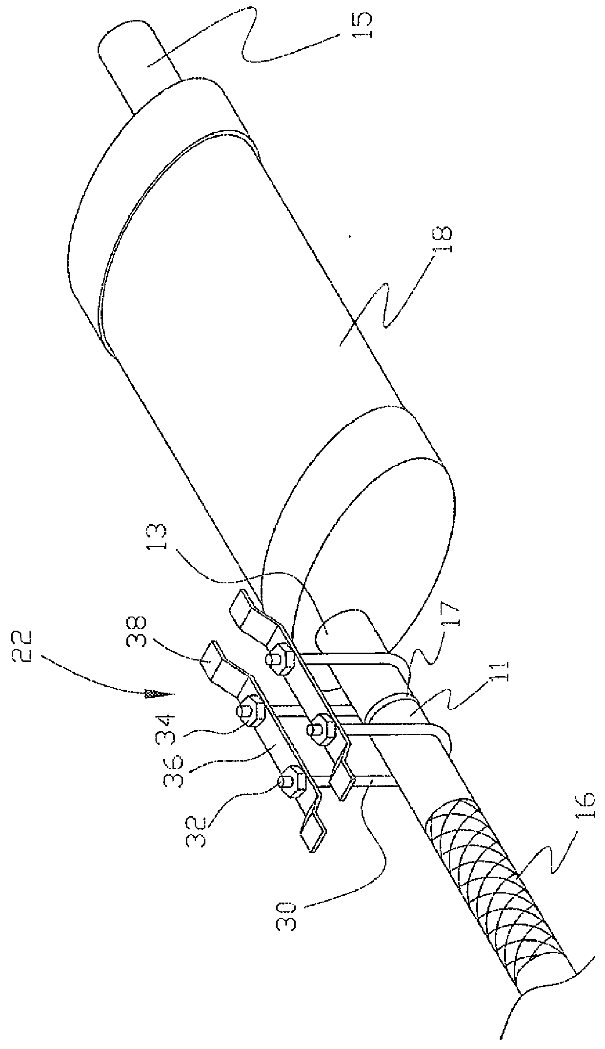
[0029]FIG. 1 shows a specific structure of a support unit 22 according to the first embodiment, which may be used in an exhaust system 10 for a vehicle in conjunction with the exhaust manifold 12, the pipe 20, the catalytic converter 14, the resonator 16 and the muffler 18 of FIG. 7.

[0030]In the drawing, the support unit 22 is composed of two U-shaped rods 30 and two combination sheets 36. Each U-shaped rod 30 has two screw sections 32. The screw sections 32 are formed on different ends of the U-shaped rod 30, and several nuts 34 are screwed to the corresponding screw sections 32. Each combination sheet 36 has an arched configuration and two ends defined with fixing portions 38. Each fixing portion 38 is welded to the bottom portion of the vehicle, so that the combination sheet 36 is kept in a fixed state. The two screw sections 32 pass through the middle portion of the combination sheet 36, which is blocked by the nuts 34 to support the two U-shaped rods 30 on two sides of a weldin...


PUM


Abstract

An exhaust system comprises a pipe disposed in a vehicle, and a resonator and a muffler, both of which are combined together and have inner chambers communicating with each other and commonly disposed on the pipe. The exhaust system further has a support unit capable of restricting vibration amplitudes of the resonator and the muffler relative to the vehicle. Thus, the exhaust system effectively solves the problem that a welding portion of the conventional exhaust system tends to break, and prevents the combustion and horse power from encountering the nonessential influence.

Description

BACKGROUND OF THE INVENTION(1) Field of the Invention[0001]The invention relates to the exhaust field for a vehicle, and more particularly to an exhaust system applicable to the vehicle.(2) Description of the Prior Art[0002]The vehicle is one of traffic tools. A good gas supply system needs to be used to provide the exploding combustion and horse power. The gas supply system is divided into the intake and the exhaust. No smooth intake can be provided when no smooth exhaust back pressure occurs.[0003]Next, the basic principle of an exhaust system 10 will be introduced with reference to FIG. 7. An exhaust manifold 12 (also referred to as an exhaust head section), a catalytic converter 14, a resonator 16 and a muffler 18 are disposed on a pipe 20.[0004]The exhaust manifold 12 has a diverging end and a converging end. The diverging end is connected to an engine (not shown), and the converging end is connected to the pipe 20. When the cylinder of the engine performs an intake operation a...

Claims


Application Information

Patent Timeline
IPC IPC(8): F01N1/02F01N13/18
CPCF01N13/1805F01N1/02F01N13/1816F01N13/1822
Inventor SHI, ZHAOSONG
Owner SHI ZHAOSONG
Why Eureka
Try Eureka