Coupling and closure apparatus for dispensing valve assembly

Inactive Publication Date: 2005-02-01
COLDER PRODS
View PDF11 Cites 66 Cited by
  • Summary
  • Abstract
  • Description
  • Claims
  • Application Information

AI Technical Summary

Benefits of technology

The embodiments of the present invention offer many advantages. For instance, interlock features of the closure and the coupler allow for a secure connection of the fluid dispensing assembly preventing the closure and the coupler from pulling apart when in an open configuration. Also, the locking member feature allows opening of the coupler when the coupler is attached to the closure. Similarly, the locking member may lock the coupler to prevent opening of the coupler when the coupler is not attached to a closure. Further, the locking member locks the coupler in its uncoupled state and ensures proper orientation is preserved between the coupling and the closure in their closed positions. Locking the coupler in the closed position prevents air from being introduced into the dispensing system and from fluid draining fro

Problems solved by technology

However, since the conventional coupling valves may include many parts made separately by using different materials, it is difficult to reduce the cost.
Further, some conventional coupl

Method used


Image

  • Coupling and closure apparatus for dispensing valve assembly
  • Coupling and closure apparatus for dispensing valve assembly
  • Coupling and closure apparatus for dispensing valve assembly

Examples


Example

In the following description of the specific embodiments, reference is made to the accompanying drawings which form a part hereof, and in which is shown by way of illustration the specific embodiments in which the invention may be practiced. It is to be understood that other embodiments may be utilized as structural changes may be made without departing from the scope of the present invention.

This invention provides a fluid dispensing assembly for fluid dispensing and fluid transmitting from a fluid source to a fluid dispensing system. The fluid dispensing assembly has a closure connected to a coupler.

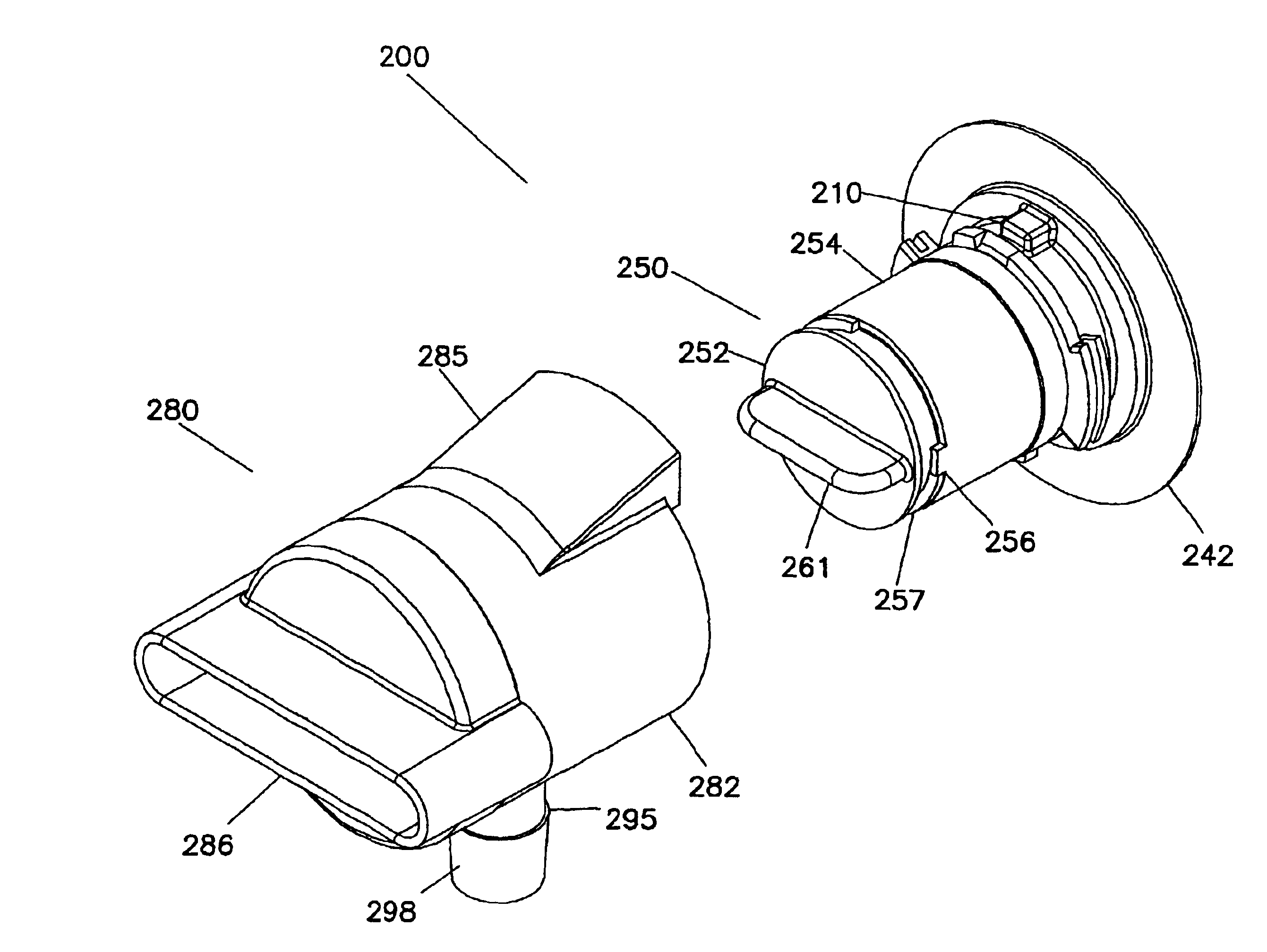
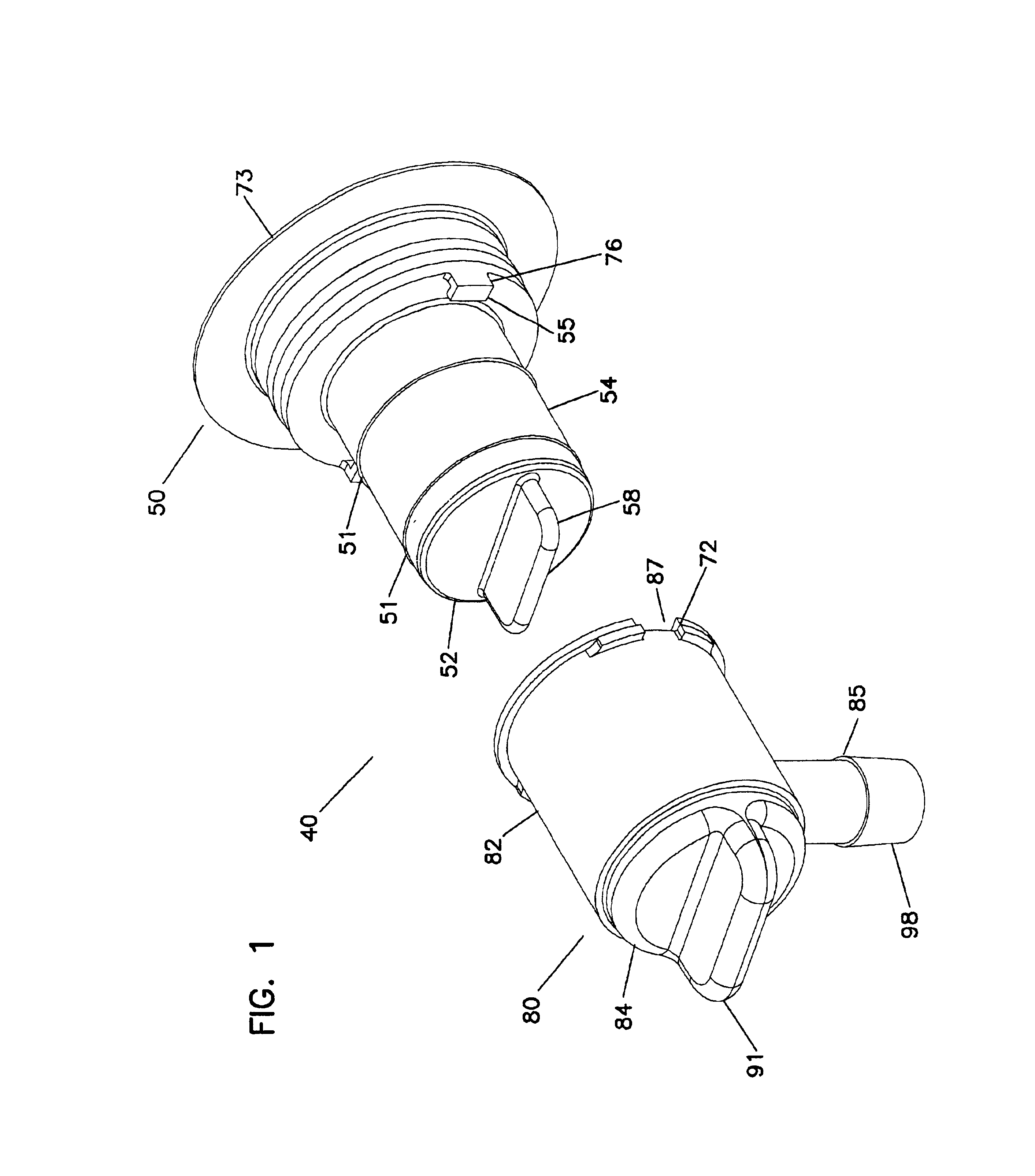
FIG. 1 illustrates a fluid dispensing assembly 40 according to one embodiment of the present invention. The fluid dispensing assembly 40 includes a closure 50 and a coupler 80 rotatably connected thereto. The closure 50 includes a closure body 54 and a closure valve 52 rotatably connected and forming a fluid tight seal.

The closure body 54 includes seals 51 which may be molded-in seals ...


PUM

PropertyMeasurementUnit
Areaaaaaaaaaaa

Abstract

A fluid dispensing assembly for fluid dispensing and fluid transmission from a fluid source. The fluid dispensing assembly alone may dispense from a fluid source, or may be connected to a fluid dispensing system. The fluid dispensing assembly has a closure connected to a coupler. The closure includes fill through capabilities. The coupler is provided with a locking feature for preserving proper orientation and a closed position before being coupled to a piece of fluid dispensing equipment.

Description

FIELD OF THE INVENTIONThis invention is related to a closure connected to a coupler. Particularly, this invention is related to a closure and a coupler used in a dispensing valve assembly.BACKGROUND OF THE INVENTIONDispensing valves are widely used in the foodstuffs industry, such as for dispensing condiments including for example, ketchups and mustards, or for dispensing other fluid like foods such as milk, or the like. Typically, a conventional coupling valve includes a first end and a second end to define a flow passage therethrough. The first end is connected to a fluid dispensing system, and the second end is used for fluid dispensing. By controlling a handle or lever of the coupling valve, the coupling valve is actuatable between an open configuration to allow fluid flow and a closed configuration to prevent fluid flow.However, since the conventional coupling valves may include many parts made separately by using different materials, it is difficult to reduce the cost. Further...

Claims


Application Information

Patent Timeline
IPC IPC(8): B67D3/04B67D3/00F16L37/252F16L37/38F16L37/28F16L37/00
CPCB67D3/045F16L37/38F16L37/252B67D3/047
Inventor DECLER, CHARLES PETERJOHNSON, ROBERT K.
Owner COLDER PRODS
Why Eureka
Try Eureka