Printer

a printing machine and printing plate technology, applied in the field of printing machines, can solve the problems of wasteful space occupation, troublesome work, and the protruding sheet feed tray and print tray from the housing, and achieve the effect of saving spa

Inactive Publication Date: 2005-02-01
RICOH KK
View PDF17 Cites 139 Cited by
  • Summary
  • Abstract
  • Description
  • Claims
  • Application Information

AI Technical Summary

Benefits of technology

It is an object of the present invention to provide a printer facilitating manual work for opening and closing a sheet inlet and a sheet outlet.
It is another object of the present invent...

Problems solved by technology

The problem with this configuration is that the sheet feed tray and print tray both protrude from the housing and therefore occupy an extra space in addition to a space occupied by the housing.
This is more serious when the sheet feed tray and print tray are respectively mounted on the front and rear o...

Method used


Image

  • Printer
  • Printer
  • Printer

Examples


first embodiment

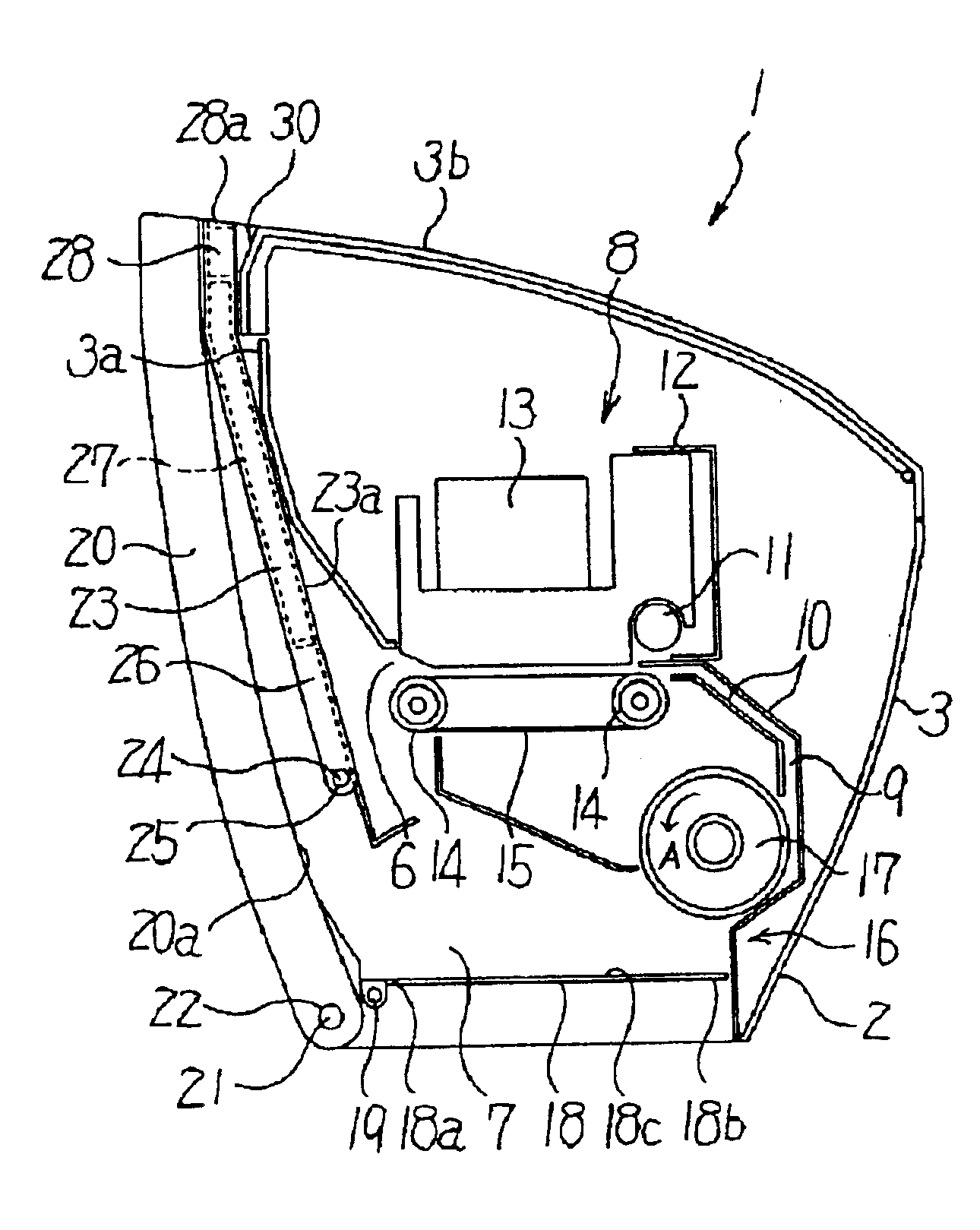
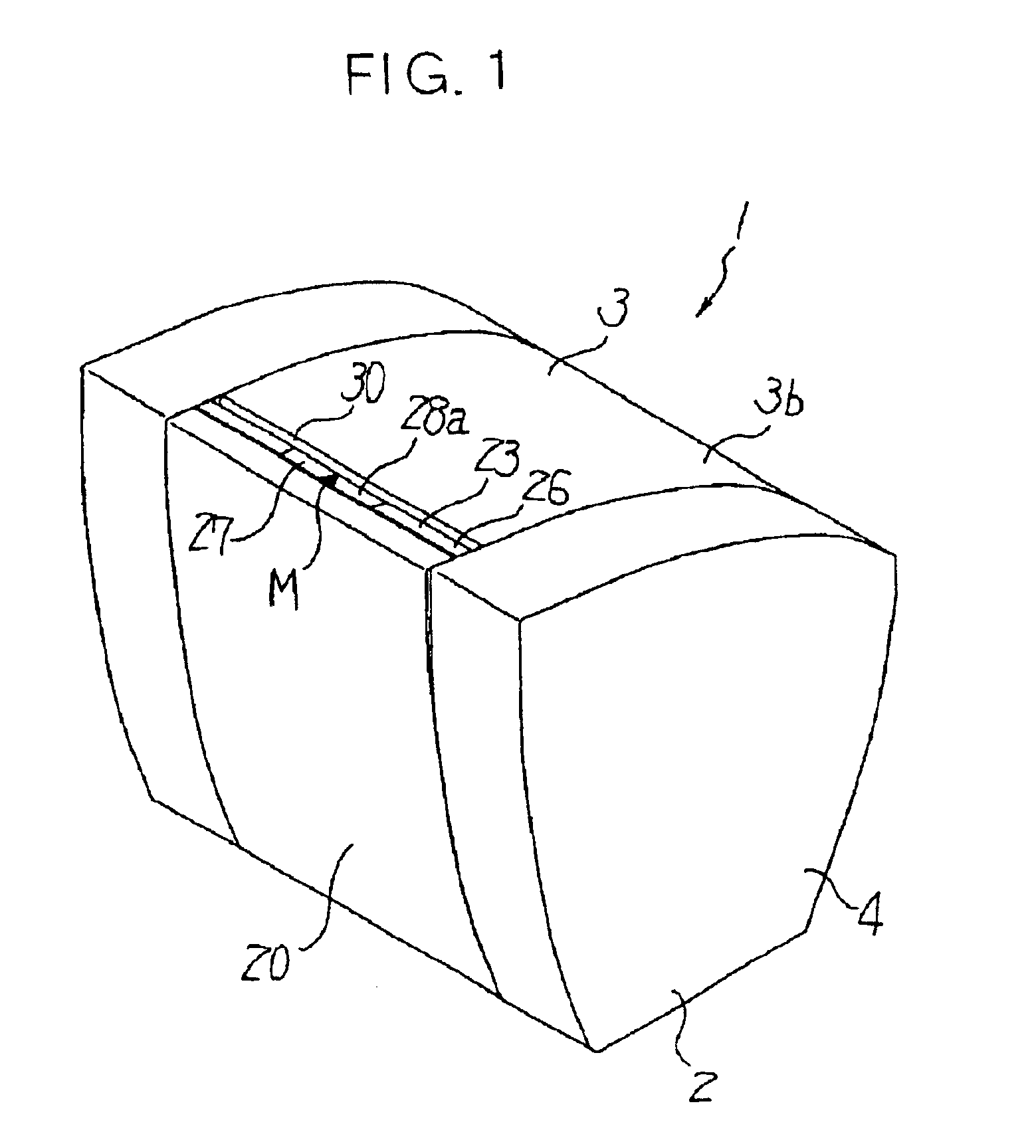
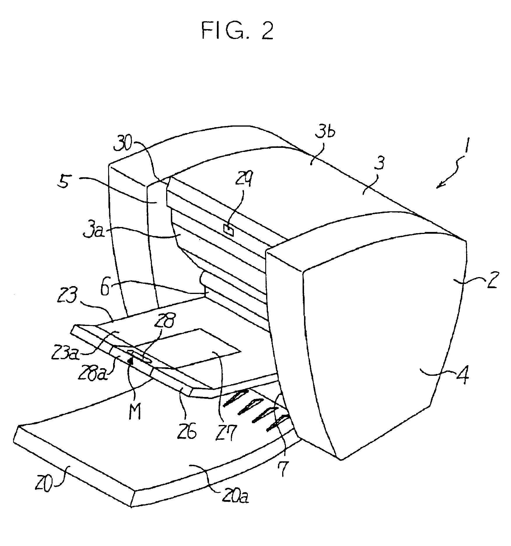
Referring to FIGS. 1 through 4, an ink jet printer embodying the present invention is shown. As shown, the ink jet printer, generally 1, includes a housing or body 2 made up of a main housing 3 and side covers 4 mounted on both sides of the main housing 3 in the main scanning direction (direction perpendicular to the sheet surface of FIG. 3). The main housing 3 is sized smaller than the side covers 4 in the subscanning direction (right-and-left direction in FIG. 3), so that a hollow 5 is formed at the front of the housing 2. The hollow 5 has a size corresponding to a difference in size between the main housing 3 and the side covers 4 and extends inward front the front (left-hand side of FIG. 3) of the housing 2. The hollow 5 is sized larger than the sheet size available with the printer 1 in the main scanning direction.

In the illustrative embodiment, the front end of the main housing 3, which forms part of the hollow 5, implements an upright wall 3a. The upright wall 3a is formed wi...

second embodiment

A second embodiment of the ink jet printer in accordance with the present invention will be described hereinafter with reference to FIGS. 6A and 6B. As shown, the printer, generally 40, includes a locking mechanism 41 for locking the sheet feed tray 20 and print tray 23 in the full-closed positions. The locking mechanism 41 is made up of a hole 42 formed throughout the print tray 23, a recess 43 formed in the sheet feed tray 20, and a lug 44 protruding from the front end of the top cover 3b. The lug 44 is configured to mate with the recess 43 via the hole 42.

The stubs 21 of the sheet feed tray 20 and the stubs 24 of the print tray 23 are respectively received in the bearings 22 and 25 via annular, slide resistance members 45, which are respectively fitted on the stubs 21 and 24. The slide resistance member 45 fitted on each stub 21 and the slide resistance member 45 fitted on each stub 24 play the role of a first and a second regulating member, respectively. In the illustrative embo...

third embodiment

A third embodiment of the ink jet printer in accordance with the present invention will be described with reference to FIGS. 8 and 9. As shown, the ink jet printer, generally 49, includes a print tray 50. Stubs 54 protrude from opposite sides of the print tray 50 and are rotatably supported by bearings 55, which are mounted on the housing 2, via slide resistance members 45 fitted on the stubs 54. The print tray 50 is therefore angularly movable about the stubs 54.

The print tray 50 includes two tray parts 52 and 53 connected to each other by a flexible member 51 and adjoining the grip 28 and stubs 54, respectively. The subtray 27 with the grip 28 is mounted on the tray part 52 in such a manner as to be slidable relative to the tray part 52. The flexible member 51 yields when subjected to an external force weaker than a frictional force, which acts between the stubs 54 and the bearings 55 because of the slide resistance bearings 45, or restores its original shape when released from su...


PUM


Abstract

A printer of the present invention includes a first and a second tray each being movable between a full-closed position and an open position. When the operator moves the first tray in the opening direction, the first tray forces the second tray located on the locus of movement of the first tray in the opening direction, uncovering a first and a second opening at the same time. When the operator moves the second tray in the closing direction, the second tray forces the first tray located on the locus of movement of the first tray in the closing direction, covering the two openings at the same time. The operator can therefore move the two trays by a single action.

Description

BACKGROUND OF THE INVENTION1. Field of the InventionThe present invention relates to a printer for personal use to be set on, e.g., a desk.2. Description of the Background ArtA printer of the type including a housing formed with a sheet inlet and a sheet outlet and a printer section arranged in the housing is conventional. In this type of printer, a sheet path provides communication between the sheet inlet and the sheet outlet via the printer section, so that the printer section can print an image on a recording medium being conveyed along the sheet path.When the recording medium is implemented as a sheet, it is a common practice to locate a sheet feed tray, a print tray or similar member for positioning the sheet or the resulting print in the vicinity of a sheet inlet or a sheet outlet. Such a member can position a plurality of sheets in the vicinity of the sheet inlet or the sheet outlet, so that images can be sequentially printed on a plurality of sheets without interruption.For ...

Claims


Application Information

Patent Timeline
IPC IPC(8): B41J29/02B41J13/10B41J29/13B41J29/12B41J13/00B65H1/04B65H31/00
CPCB41J13/103B41J29/13B41J29/02B41J13/106
Inventor KATSUYAMA, GORO
Owner RICOH KK
Why Eureka
Try Eureka