Platform for raising the bindings for a boot, and board for gliding over snow equipped with such a platform

a technology the platform is applied in the field of platforms for raising the bindings of the boot and the platform is equipped with such a technology, which can solve the problems of lack of flexibility between the two mounting zones, difficult assembly of the platform arrangement, and relatively heavy weigh

Inactive Publication Date: 2005-02-01
SKIS ROSSIGNOL
View PDF26 Cites 34 Cited by
  • Summary
  • Abstract
  • Description
  • Claims
  • Application Information

AI Technical Summary

Benefits of technology

[0009]The object of the invention is to propose a board for gliding over snow with a platform which is lighter by virtue of a choice of shape and which, moreover, makes it possible to separate the left and right bearing forces so as to transmit the forces applied by the user onto the board and the forces generated more directly in the region of the left edge or the right edge.

Problems solved by technology

The main drawback of this platform is the absence of flexibility which may exist between the two mounting zones which are fully coupled mechanically both by the central support elements and by the two rigid end plates.
Furthermore, this type of platform arrangement is difficult to assemble and is relatively heavy.

Method used


Image

  • Platform for raising the bindings for a boot, and board for gliding over snow equipped with such a platform
  • Platform for raising the bindings for a boot, and board for gliding over snow equipped with such a platform
  • Platform for raising the bindings for a boot, and board for gliding over snow equipped with such a platform

Examples


eleventh embodiment

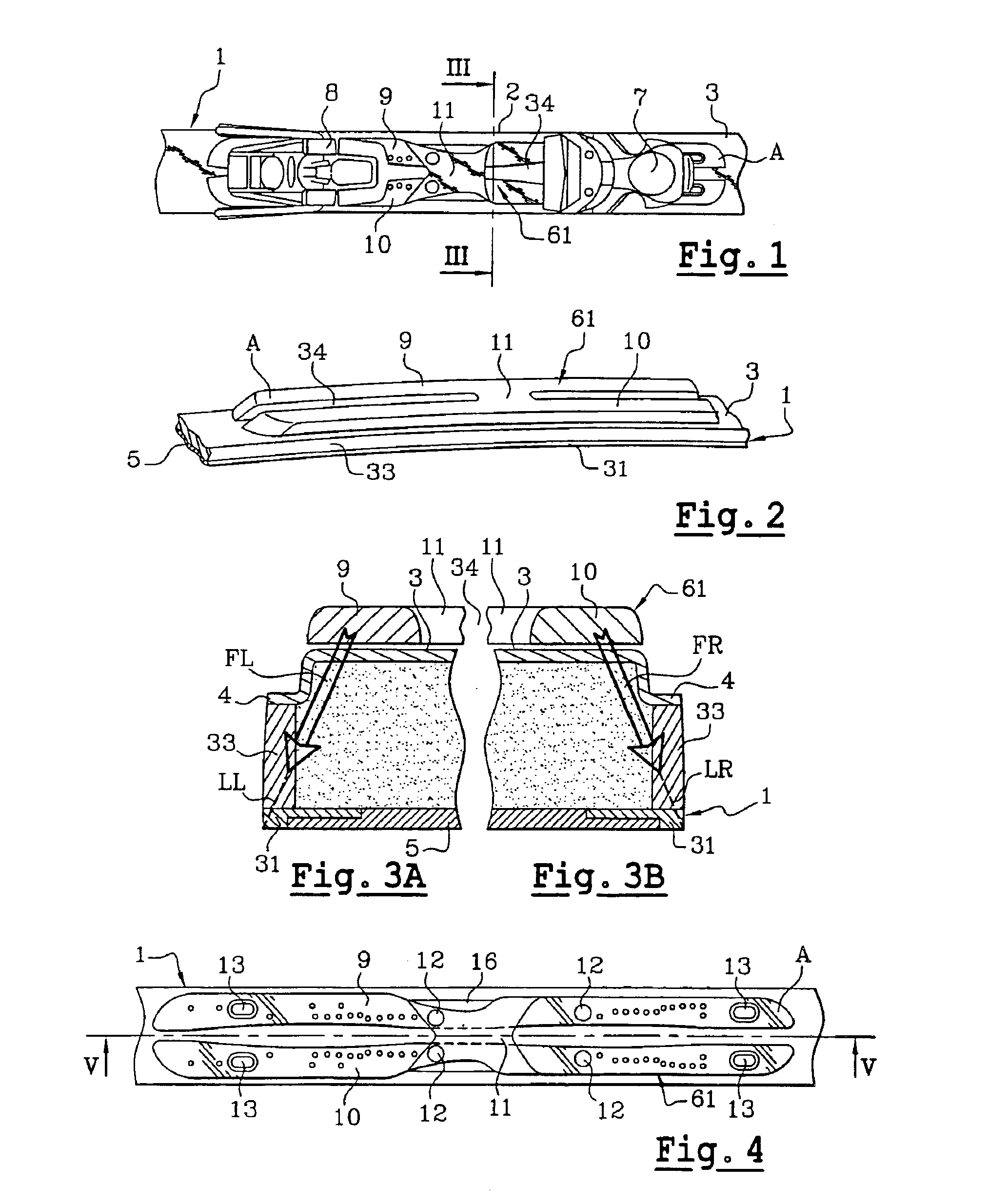
42]FIG. 15 shows a top view of a platform according to an eleventh embodiment, mounted on a ski in partial view;

[0043]FIG. 16 shows a partial view in longitudinal section of the ski and its platform in the plane XVI—XVI in FIG. 15;

[0044]FIG. 17 shows a transverse-sectional view of a ski with a platform according to a twelfth embodiment;

[0045]FIG. 18 shows a partial lateral view of a ski with a platform according to a thirteenth embodiment;

[0046]FIG. 19 shows a partial lateral view of a ski with a platform according to a fourteenth embodiment;

[0047]FIG. 20 shows a partial lateral view of a ski with a platform according to a fifteenth embodiment;

[0048]FIG. 21 shows a partial lateral view of a ski with a platform according to a sixteenth embodiment;

[0049]FIG. 22 shows a partial lateral view of a ski with a platform according to a seventeenth embodiment; and

[0050]FIG. 23 shows a transverse-sectional view in the plane XXIII—XXIII in FIG. 20 of a ski with its platform according to the fif...

first embodiment

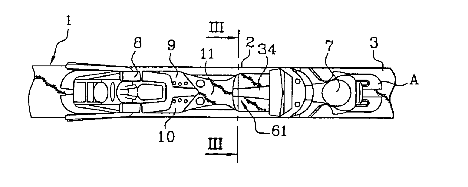
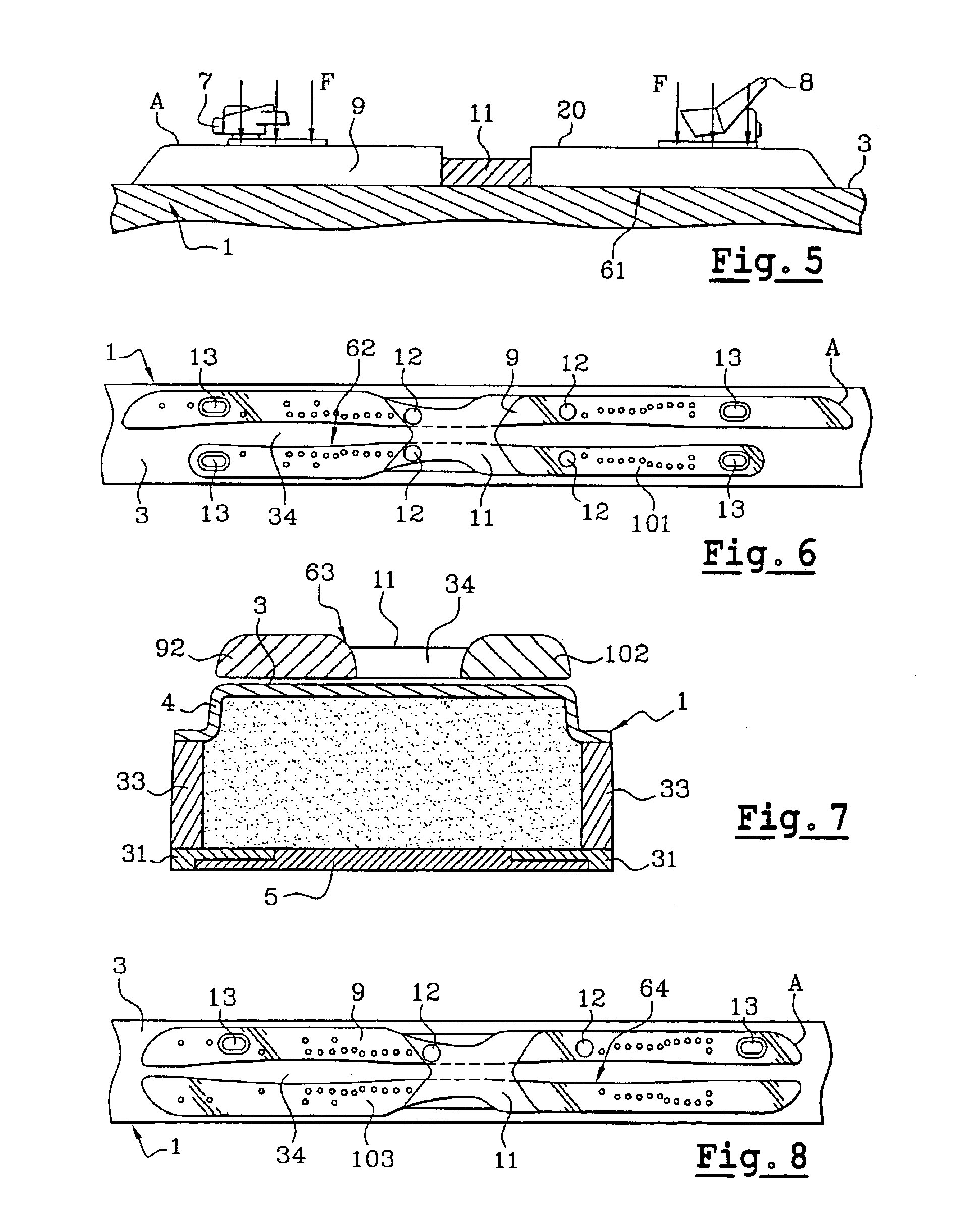
[0054]The platform (61) is divided into two along the central longitudinal axis of the ski (1) and therefore comprises two rigid longitudinal parts (9 and 10). According to the invention, and in a first embodiment, a bridge (11) connects the two rigid longitudinal parts (9 and 10) in their median zone. In other words, the platform (61) comprises two slots made in the region of its median longitudinal axis, i.e. also in the region of the median longitudinal axis of the ski (1), and emerging toward the front (A) and toward the rear.

[0055]The bridge (11) is positioned in a portion outside the securing for the elements of the binding (7 and 8). In order to allow transmission of the forces between one of the longitudinal parts (9) and the edge (31) associated with it, the bridge (11) will be located between the zones of transmission of the forces (F) (see FIG. 5) of the skier on the platform (61), i.e. between the front and rear supports of the ski boot. The transmission of the forces (F...


PUM


Abstract

A raising platform (6) is intended for mounting on the upper surface (3) of a board (1) for gliding over snow in order to receive and to raise the bindings securing a user's boot to a board (1) for gliding over snow.
The raising platform (6) is divided into two longitudinal parts (9, 10) that are each placed directly on the upper surface (3) of the board (1) for gliding over snow and that are connected together by at least one bridge (11).

Description

[0003]The present invention relates to a platform for raising the bindings for a boot of a user of a board for gliding over snow.[0004]The present invention also relates to a board for gliding over snow, such as a ski, a monoski or a snowboard, equipped with a platform for raising the bindings for a boot.[0005]A platform for raising the bindings is attached in the underfoot zone of a board for gliding, in the region of its upper surface. The platform is fixed to the board either directly by means of screws, in order to obtain a rigid link, or by virtue of elastic return means in the form, for example, of a layer of material having damping properties.STATE OF THE ART[0006]A platform is known from document EP-1,023,926, which has the form of two central support elements on which two distinct longitudinal uprights are placed in an overhanging fashion. Two rigid plates connecting the two mounting zones in pairs are screwed to each of the two ends of the two longitudinal uprights to make...

Claims


Application Information

Patent Timeline
Patent Type & Authority Patents(United States)
IPC IPC(8): A63C9/00
CPCA63C9/003
Inventor GODDE, JEAN-CHRISTOPHEREDOR, DENISSTEFANOVA, MILENA
Owner SKIS ROSSIGNOL
Why Eureka
Try Eureka