Portable lantern

a fuel-burning lantern and portable technology, applied in the field of lanterns, can solve the problems of affecting the operation of the lantern, the refueling process is typically messy, and the conventional fuel-burning lantern is usually too large for storage, so as to achieve the effect of low cost, reliable and safe operation, and compact construction

Inactive Publication Date: 2005-02-01
THE COLEMAN CO INC
View PDF46 Cites 3 Cited by
  • Summary
  • Abstract
  • Description
  • Claims
  • Application Information

AI Technical Summary

Benefits of technology

In an exemplary embodiment, the present invention provides a rugged and compact lantern comprising a refillable fuel storage tank, a fuel delivery sub-system, a burner with a mantle and reflector, a globe, a ventilator with a heat shield, a plastic housing, movable shields to protect the globe in transport, and a bail for hanging and / or carrying the lantern.
In an exemplary embodiment, a lantern in accordance with the present invention comprises a novel structure which allows fast and easy assembly of the lantern with minimal tools.
In other aspects, the present invention provides a novel fuel-filling mechanism, a novel mechanism for removably attaching a mantle and a novel latch that is formed integrally with a plastic housing member.
A lantern in accordance with the present invention can be built compactly and at a low cost, while operating reliably and safely under a variety of conditions.

Problems solved by technology

Conventional fuel-burning lanterns can be quite bulky and are usually too large for storage in a small carrier such as a backpack.
Their usually fragile construction also makes them susceptible to damage in transport and in use.
Moreover, refueling is typically a messy procedure, usually requiring pouring a liquid fuel into an opening using a funnel.
In the alternative, expendable fuel canisters are required, which can be quite costly.

Method used


Image

  • Portable lantern
  • Portable lantern
  • Portable lantern

Examples


Embodiment Construction

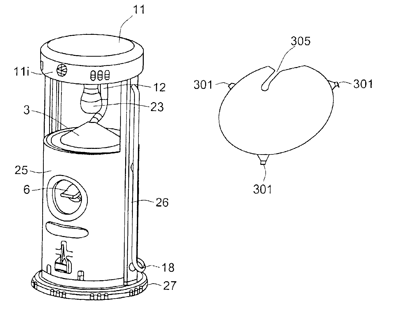
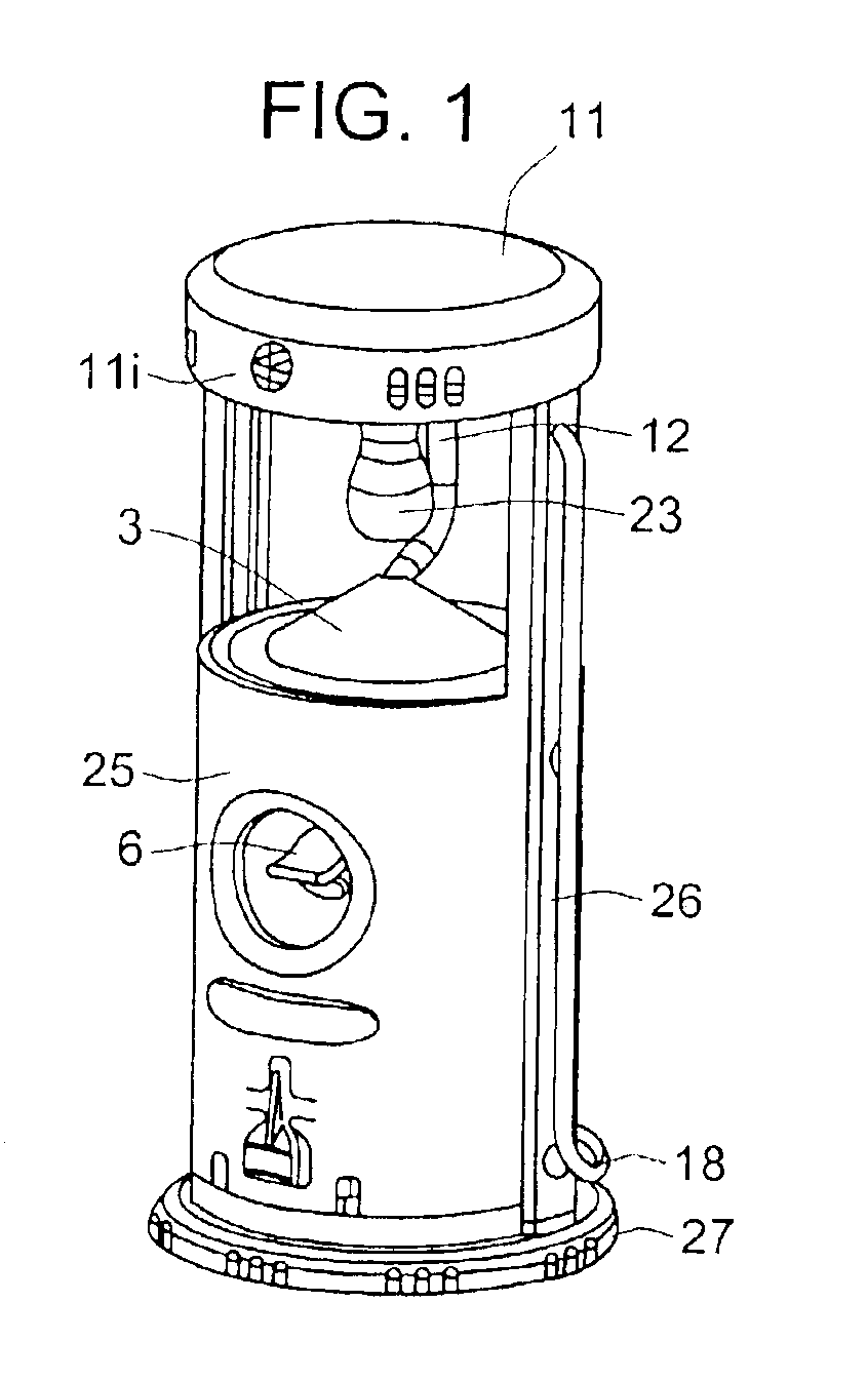
FIG. 1 shows a perspective view of an exemplary embodiment of a lantern in accordance with the present invention. As shown, the exemplary lantern has a generally cylindrical shape which is well-suited for such an application, although other shapes are possible within the scope of the present invention. The lantern comprises a globe 1 which encloses a burner tube 12 having a mantle 23 attached thereto. When lit, the mantle 23 provides illumination through the globe 1, which is preferably comprised of transparent glass. The mantle 23 is implemented in a known way, such as a fabric impregnated with yttrium oxide. The globe 1 and burner sub-assembly are arranged on a housing 25 which houses fuel storage and delivery sub-systems, described more fully below. A knob 6 is coupled to a fuel control valve for controlling the supply of fuel to the burner tube 12, and thus to the mantle 23. The housing 25 sits on a removable base 27. Removing the base 27 provides access to the fuel storage sub-...


PUM


Abstract

A lantern having a compact configuration. The lantern has a generally cylindrical shape with a lower housing containing a fuel tank, a shut-off valve and a regulator. A cap at the base of the lower housing can be removed, providing access to the fuel tank. The fuel tank is refillable via a fuel fill valve arranged at the base of the tank. A burner tube is coupled to the regulator and extends upwards beyond the housing. A mantle is removably coupled to the upper end of the burner tube. A generally conical reflector is arranged around the burner tube below the mantle and above the regulator. A glass globe is arranged around the burner tube / mantle assembly and a ventilator cap is arranged above the globe. The ventilator cap attaches to rails which extend up from opposite sides of the lower housing and can be readily removed to access the mantle.

Description

FIELD OF THE INVENTIONThe present application relates to lanterns, particularly to portable, fuel-burning lanterns.BACKGROUND INFORMATIONA conventional fuel-burning lantern typically comprises a refillable fuel storage tank, fuel delivery means, and a burner attached to the fuel delivery means. The burner typically comprises a mantle which when ignited with a fuel / air mixture provided by the fuel delivery means emits a bright light. The burner is usually covered by a transparent glass globe. Fuel typically used with such lanterns includes liquid propane, butane, white gas and gasoline.Conventional fuel-burning lanterns can be quite bulky and are usually too large for storage in a small carrier such as a backpack. Their usually fragile construction also makes them susceptible to damage in transport and in use. Transporting a conventional lantern in a carrier typically requires that the lantern be placed within its own protective enclosure. Moreover, refueling is typically a messy pro...

Claims


Application Information

Patent Timeline
Patent Type & Authority Patents(United States)
IPC IPC(8): F21S13/12F21L19/00F21S13/00F21V19/06
CPCF21L19/00F21V19/06F21S13/12
Inventor LONG, NORRIS RICHARD
Owner THE COLEMAN CO INC
Why Eureka
Try Eureka