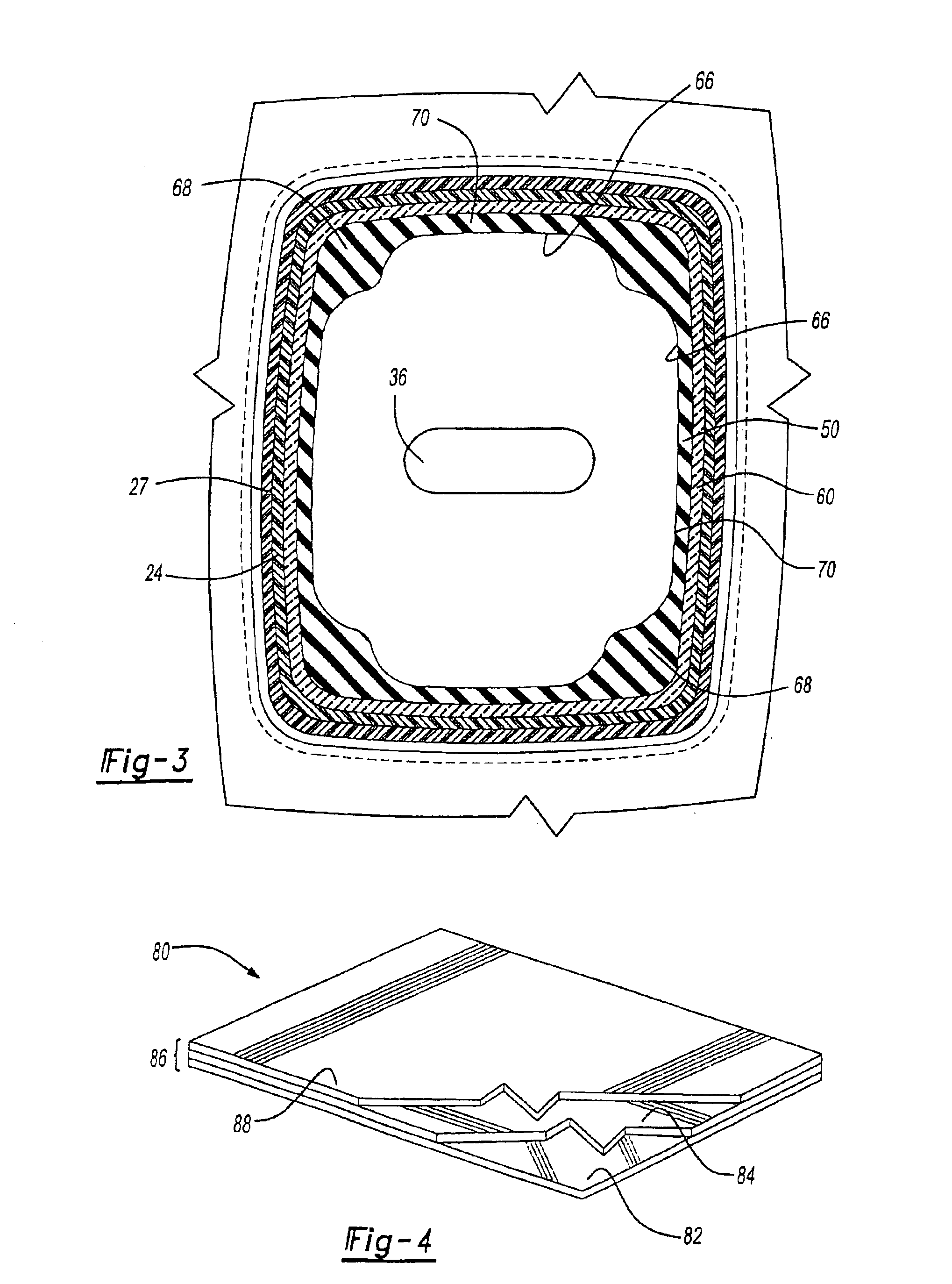
The switch mat of the present invention further includes the stepped portion having a shoulder located a predetermined distance away from the first end of the projection for limiting travel of a button relative to the projection. And, the second end of the projection is connected to the generally planar sheet. In addition, the inner surface of the projection has
variable thickness that is created by at least one axial groove provided on the projection for increasing interior cross-sectional area for light to pass to the at least one button for fully illuminating any indicia thereon. Further, the projection includes corners having a cross-sectional thickness greater than an adjacent side wall portion for insuring lateral strength of the projection. One disclosed version includes the projection having a generally rectangular cross-sectional shape.
Another method step of the present invention involves applying a third layer of material onto the coextruded first and second
layers. The step of applying can be carried out by at least one of thermally bonding, spraying, or printing. Still further, the forming step is optionally, but preferably performed after the step of applying the third layer to improve
processing and quality. More specifically, the step of forming can include
vacuum forming.
The present invention provides a control panel
assembly and components that are more cost effective to fabricate and eliminates extra steps that are required to make previously known components. Control panel components provided in accordance with the present invention have an inner transparent layer, a middle translucent color layer, and an opaque outer surface layer. Indicia can be provided on the button or bezel using a
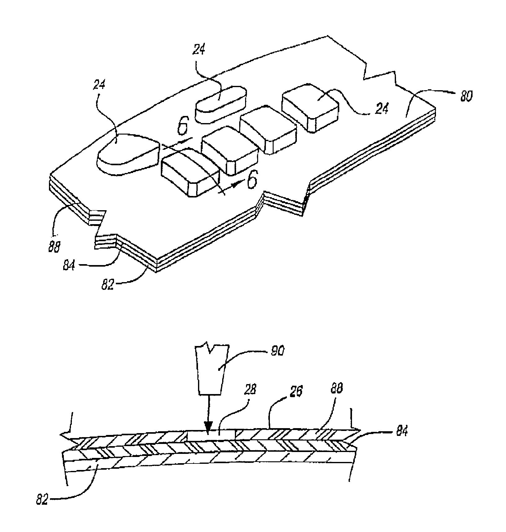
laser etching technique that removes a predetermined portion of the opaque outer surface layer. The component can be vacuum formed from a multi-layer sheet that includes a co-extruded substrate having a generally transparent layer co-extruded with one or more translucent color
layers. A thin outer opaque layer is thermally bonded to the co-extruded substrate using residual heat remaining from the co-
extrusion process. Next the multi-layer sheet is vacuum formed to create a any number of components. As a result, the steps of painting multiple coats and
drying each coat has been eliminated. Thus, environmental concerns associated with painting are eliminated. Further, the present invention provides a more uniform thickness to the outer opaque layer than is provided by painting. Moreover, the inner transparent layer is made sufficiently thick to provide adequate strength for the button, thereby eliminating the need to injection mold resin behind the button as in the prior art. By eliminating the injection molding step, the present invention substantially reduces tooling costs and tooling time versus known button making processes. In addition,
cycle time to process the button is reduced from approximately 30 seconds to approximately 6 seconds. Therefore, costs of fabricating buttons is substantially reduced in accordance with the present invention.
The control panel
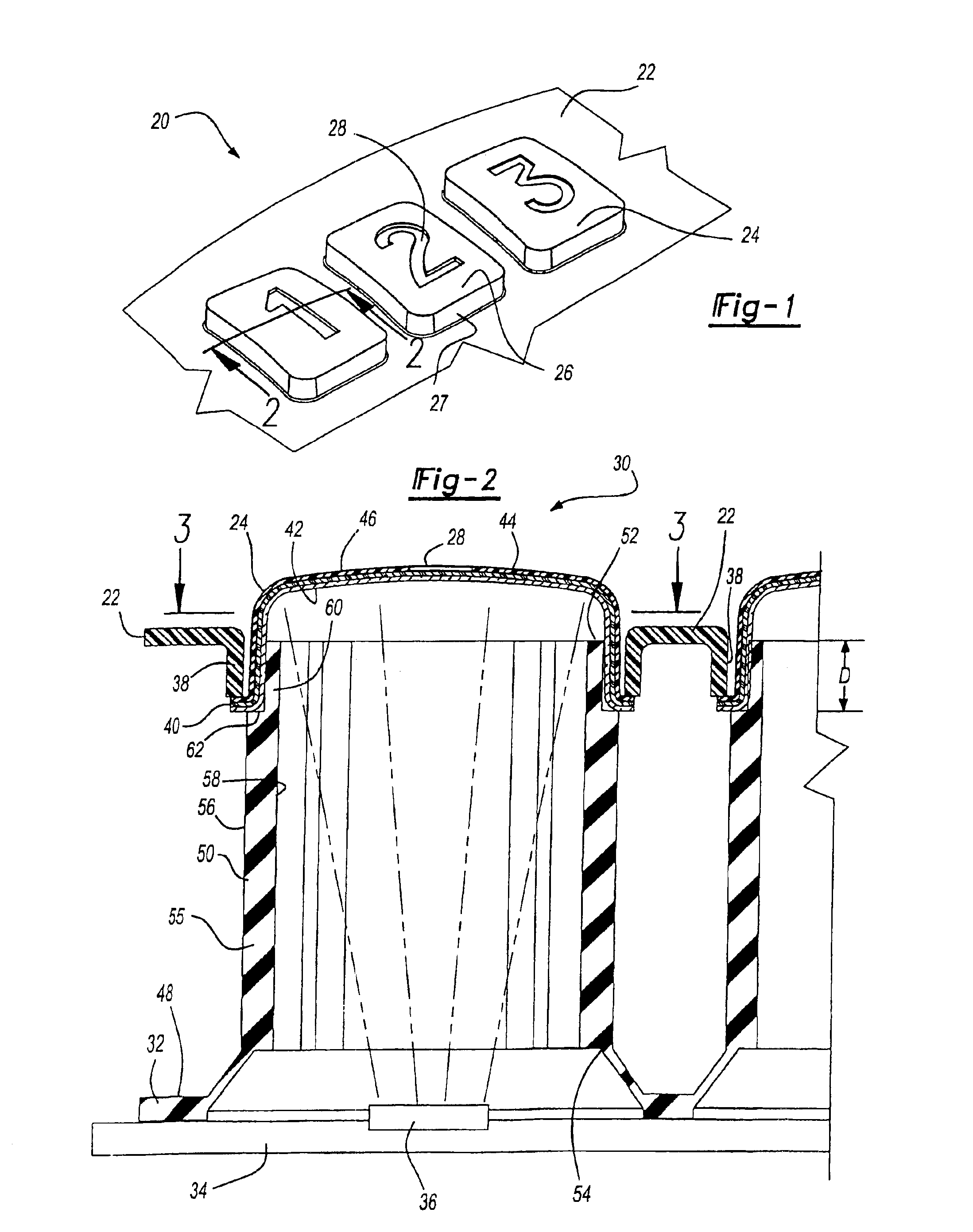
assembly of the present invention further includes an elastomeric switch mat having a planar sheet portion with a plurality of projections that correspond to locations of buttons. Each projection has first and second ends and are generally hollow having side walls with inner and outer surfaces. The switch mat covers a
printed circuit board having a
light source. A projection channels light from the
light source up to the button mounted thereon and allows the button to be backlit. Preferably, a stepped portion is provided at the first end of the projection for receiving the button. A shoulder is provided to act as a stop which limits the travel of the button onto the projection and spaces the inner surface layer of the button away from the first end of the projection to enable the
light source to fully illuminate any indicia located on the button. Moreover, the side walls of the projections have
variable thickness and include axial grooves to allow light to reach the inner surface layer of the button. The present invention therefore allows buttons having greater arcuately shaped or contoured top surfaces to be used without the drawback of having idicia being blocked off from light by a side wall of the projection.
As a result, the present invention provides a control panel assembly such as those used on the interior of automotive vehicles that are cost effective, have improved feel to the user and have indicia that will not be rubbed off during its service life.

