Switching device including stopper surface-mounted on printed circuit board

Active Publication Date: 2005-02-01
ALPS ALPINE CO LTD
View PDF13 Cites 13 Cited by
  • Summary
  • Abstract
  • Description
  • Claims
  • Application Information

AI Technical Summary

Benefits of technology

To solve the aforementioned problems associated with the known switching device, it is an object of the present invention to provide a compact switching device including a sturdy stopper that is precisely positioned at the desired position.
According to the switching device of the present invention, the stopper is separately formed from the switch body so that the switch body provides sturdy stopping function and the switch body and the stopper have small dimensions. Furthermore, since the switch body and the stopper are surface-mounted on the printed circuit board, mounting is facilitated and an additional member for fixing these components is not necessary.

Problems solved by technology

Furthermore, since the clicking mechanism is small, it cannot provide a precise indication that it has been clicked and provide a sturdy stopping function.
In this case, however, accumulated errors in fabricating or assembling the device cause larger errors or variations in the positions of the stoppers.

Method used


Image

  • Switching device including stopper surface-mounted on printed circuit board
  • Switching device including stopper surface-mounted on printed circuit board
  • Switching device including stopper surface-mounted on printed circuit board

Examples


Embodiment Construction

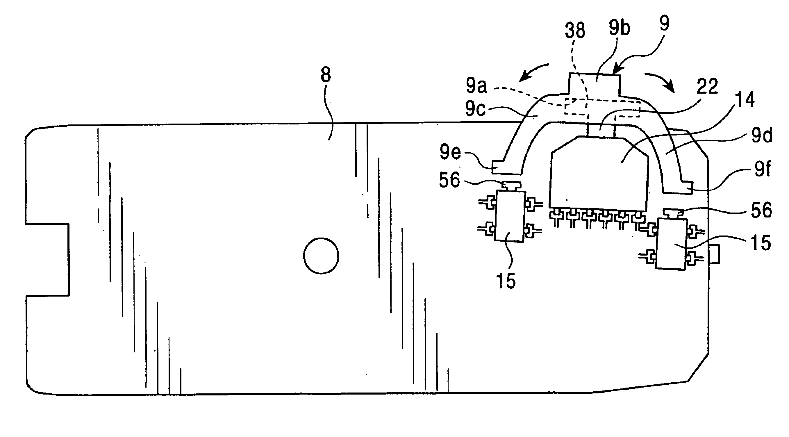
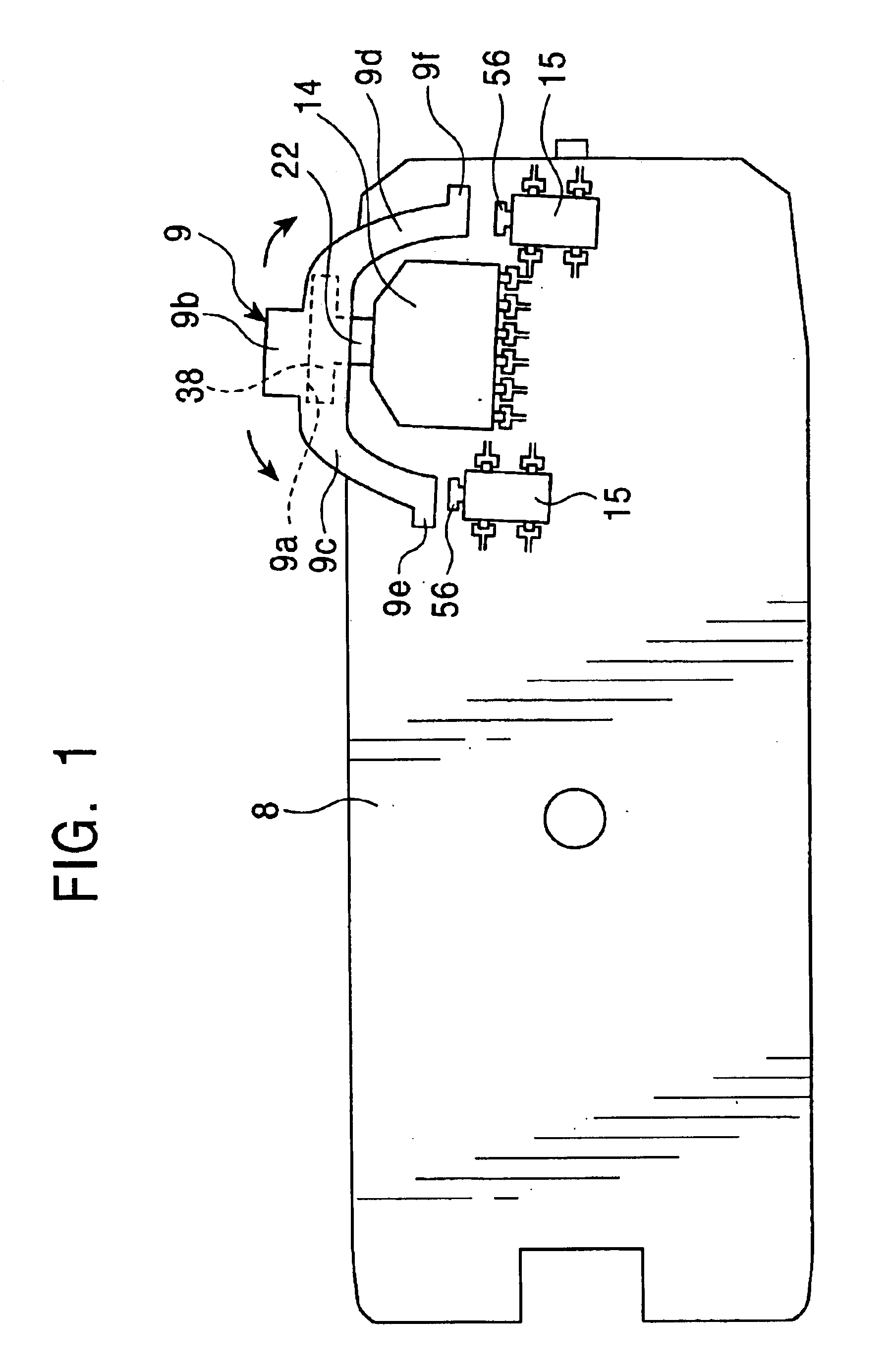
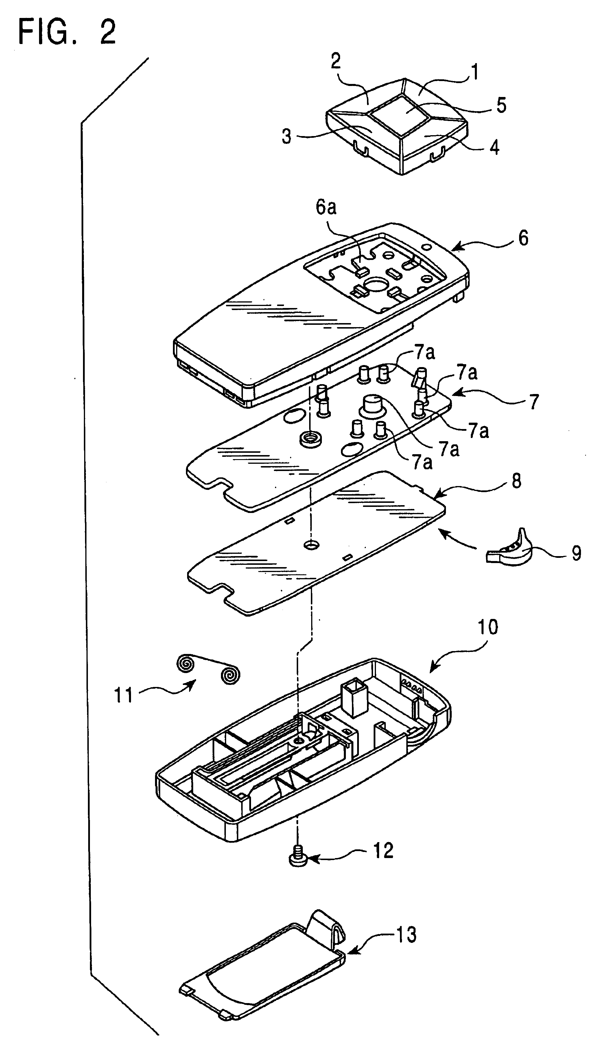
The embodiments of the present invention will now be described by referring to the accompanying drawings. FIG. 1 is a schematic view of a switching device according to an embodiment of the present invention. FIG. 2 is an exploded perspective view of the switching device. FIG. 3 is a perspective view of a switch body in the switching device. FIG. 4 is a perspective view of the switch body when it is tilted. FIG. 5 is a perspective view of the switch body when it is depressed. FIG. 6 is an exploded perspective view of the switch body. FIG. 7 is a perspective view of the switch body. FIG. 8 is a plan view of a wafer in the switch body. FIG. 9 is an exploded perspective view of a push switch according to an embodiment. FIG. 10 is a cross-sectional view of a principal portion of the push switch in which the components illustrated in FIG. 9 are assembled.

The switching device is included in a menu selection remote controller, as shown in FIG. 2. This remote controller has a top case 6, a r...


PUM


Abstract

A switching device includes a switch body, a side knob, a returning mechanism, and a stopper. The switch body has a controlling unit which can be tilted and depressed. The switch body is surface-mounted on the printed circuit board. The side knob is attached to the controlling unit of the switch body. The switch body includes the returning mechanism for the controlling unit. The stopper is actuated in accordance with the tilting or depression of the side knob. The stopper is surface-mounted on the printed circuit board.

Description

This application claims the benefit of Priority to Japanese Patent Application No. 2003-138725, herein incorporated by reference.BACKGROUND OF THE INVENTION1. Field of the InventionThe present invention relates to a switching device which can be tilted and is used in a remote controller for menu selection or the like.2. Description of the Related ArtFIG. 11 schematically illustrates a known switching device. Referring to FIG. 11, a printed circuit board 80 is provided with a seesaw switch 82 in a case 83. The seesaw switch 82 has a tilting knob 81 that is disposed on the surface of the case 83. This seesaw switch 82 further includes a returning mechanism for the tilting knob 81, two switching mechanisms, and a clicking mechanism. The two switching mechanisms are turned on when the tilting knob 81 reaches both ends of the seesaw movement. The clicking mechanism gives a clicking feeling when the seesaw switch 82 is turned on and functions as a stopper, controlling the movement of the ...

Claims


Application Information

Patent Timeline
IPC IPC(8): H01H21/24H01H21/00H01H25/00H01H19/03H01H19/00H01H25/06H01H23/16H01H23/30
CPCH01H25/008H01H21/24H01H19/03
Inventor TAKATA, TOMOSUKEUENO, HIDEKIYAMAMOTO, KOICHI
Owner ALPS ALPINE CO LTD
Why Eureka
Try Eureka