Dynamically adjusting a sample-to-pixel filter in response to user input and/or sensor input

a filter and sample-to-pixel technology, applied in the field of computer graphics, can solve the problems of increasing the complexity of the image displayed, the complexity of the data being sent to the display device, and the large amount of processing power of the graphics processor, so as to achieve the effect of less sharpness

Inactive Publication Date: 2005-02-01
ORACLE INT CORP
View PDF5 Cites 63 Cited by
  • Summary
  • Abstract
  • Description
  • Claims
  • Application Information

AI Technical Summary

Benefits of technology

In one embodiment, the sample-to-pixel calculation units may apply the adjusted filter to the filtration of samples starting with the next frame. In other embodiments, the sample-to-pixel calculation units may apply the adjusted filter to the filtration of samples starting with the frame after next frame, or more generally, with the Nth subsequent frame. In some embodiments, the graphics system may employ a level of hysteresis to prevent flickering.
In some embodiments, the filter may be dynamically adjusted in response to receiving user input. Different users may have different preferences as to the quality of an image. Certain users may prefer, for example, an image that is sharper, whereas other users may prefer an image that is less sharp and softer. Furthermore, different displays may have a different response to the same pixel values. For example, a CRT has a Gaussian intensity distribution about each pixel, while an LCD has a square intensity distribution with a sharp cut-off in intensity about every pixel. Thus, a user may be able to obtain the same visual effect from a CRT and from an LCD, for example, by dynamically adjusting the filter type, the filter function and / or the filter support.

Problems solved by technology

Modem graphics systems, however, incorporate graphics processors with a great deal of processing power.
This change is due to the recent increase in both the complexity and amount of data being sent to the display device.
Similarly, the images displayed are now more complex and may involve advanced techniques such as anti-aliasing and texture mapping.
As a result, without considerable processing power in the graphics system, the CPU would spend a great deal of time performing graphics calculations.
This could rob the computer system of the processing power needed for performing other tasks associated with program execution and thereby dramatically reduce overall system performance.
For example, an image with a high pixel density may still appear unrealistic if edges within the image are too sharp or jagged (also referred to as “aliased”).
More specifically, anti-aliasing entails removing higher size components from an image before they cause disturbing visual artifacts.
While the techniques listed above may dramatically improve the appearance of computer graphics images, they also have certain limitations.
In particular, they may introduce their own aberrations and are typically limited by the density of pixels displayed on the display device.
Prior art graphics systems have generally fallen short of these goals.
These systems, however, have generally suffered from limitations imposed by the conventional frame buffer and by the added latency caused by the render buffer and filtering.
Although the effects of filtering yield images that are typically pleasing to the eye, filtering may also generate undesirable artifacts.
As a result of this clipping, undesirable artifacts may become apparent, such as ringing or fringing (i.e. either light or dark bands echoing the edges of large transitions in intensities).
In addition to negative lobes, another impediment to realistic images is the variable nature of current display devices.
Furthermore, this situation is further complicated by different users having different preferences for the visual appearance of displayed images.
For example, what might appear as an acceptably sharp image to one user may appear to another user as excessively smoothed.

Method used


Image

  • Dynamically adjusting a sample-to-pixel filter in response to user input and/or sensor input
  • Dynamically adjusting a sample-to-pixel filter in response to user input and/or sensor input
  • Dynamically adjusting a sample-to-pixel filter in response to user input and/or sensor input

Examples


Embodiment Construction

Computer System—FIG. 1

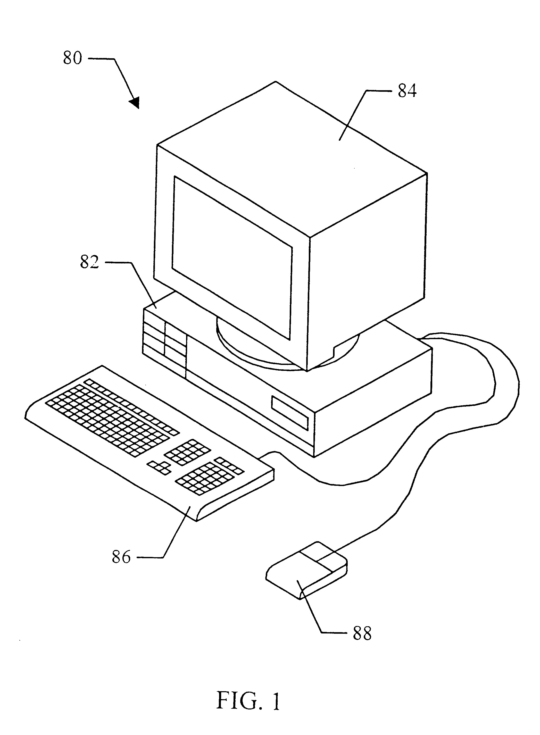
FIG. 1 shows one embodiment of a computer system 80 that includes a three-dimensional (3-D) graphics system. The computer system may be comprised in any of various systems, including a traditional PC, network PC, Internet appliance, a television, including HDTV systems and interactive television systems, set top boxes, game console, personal digital assistants (PDAs), and other devices which display 2D and or 3D graphics, among others.

As shown, the computer system 80 comprises a system unit 82 and a video monitor or display device 84 coupled to the system unit 82. The display device 84 may be any of various types of display monitors or devices (e.g., a CRT, LCD, or gas-plasma display). Various input devices may be connected to the computer system, including a keyboard 86 and / or a mouse 88, or other input device (e.g., a trackball, digitizer, tablet, six-degree of freedom input device, head tracker, eye tracker, data glove, body sensors, etc.). Application softw...


PUM


Abstract

A graphics system capable of super-sampling and performing real-time convolution. The graphics system may comprise a graphics processor, a sample buffer, and a sample-to-pixel calculation unit. The graphics processor receives graphics data and generates a plurality of samples for each of a plurality of frames. The sample buffer stores the samples. The sample-to-pixel calculation unit is operable to generate output pixels by filtering the rendered samples using a filter. A display device then receives and displays the output pixels. A user may observe the displayed image and adjust properties of the filter according to the user's personal visual preferences. A display-monitoring device may be configured to capture the displayed image. The graphics system may then analyze the captured image and, in response to the captured image, perform filter adjustments.

Description

BACKGROUND OF THE INVENTION1. Field of the InventionThis invention relates generally to the field of computer graphics and, more particularly, to high performance graphics systems.2. Description of the Related ArtA computer system typically relies upon its graphics system for producing visual output on the computer screen or display device. Early graphics systems were only responsible for taking what the processor produced as output and displaying that output on the screen. In essence, they acted as simple translators or interfaces. Modem graphics systems, however, incorporate graphics processors with a great deal of processing power. They now act more like coprocessors rather than simple translators. This change is due to the recent increase in both the complexity and amount of data being sent to the display device. For example, modem computer displays have many more pixels, greater color depth, and are able to display images that are more complex with higher refresh rates than ear...

Claims


Application Information

Patent Timeline
Patent Type & Authority Patents(United States)
IPC IPC(8): G06T17/00G06T11/20G06T15/00G09G5/00G06T11/40G06T15/50
CPCG06T15/503
Inventor DEERING, MICHAEL F.
Owner ORACLE INT CORP
Why Eureka
Try Eureka