Remote control of image sensing apparatus

a remote control and image sensing technology, applied in the field of image sensing systems, can solve the problems of inability to match the output still image, and inability to control the movement of the lens of a video camera

Inactive Publication Date: 2005-02-01
CANON KK
View PDF8 Cites 79 Cited by
  • Summary
  • Abstract
  • Description
  • Claims
  • Application Information

AI Technical Summary

Benefits of technology

[0035]The present invention has been made in consideration of the above situation, and has a

Problems solved by technology

In the aforesaid interlace scanning method, there is a problem in which, when outputting a frame (configured with two field images) of a fast moving image as a still image, the outputted still image is mismatched because of a difference between the two field images due to the movement associated with a lapse of time.
Further, in a conventional video camera which performs interlace scanning and outputs two field images as a still image of a frame, there is a problem in which, with only one flashing operation in each frame, the outputted still image is disturbed since one field image is obtained while flashing the electronic flash, whereas the other filed image is obtained without flashing the electronic flash, as shown in FIG. 6, and bright lines and dark lines are mix

Method used


Image

  • Remote control of image sensing apparatus
  • Remote control of image sensing apparatus
  • Remote control of image sensing apparatus

Examples


second embodiment

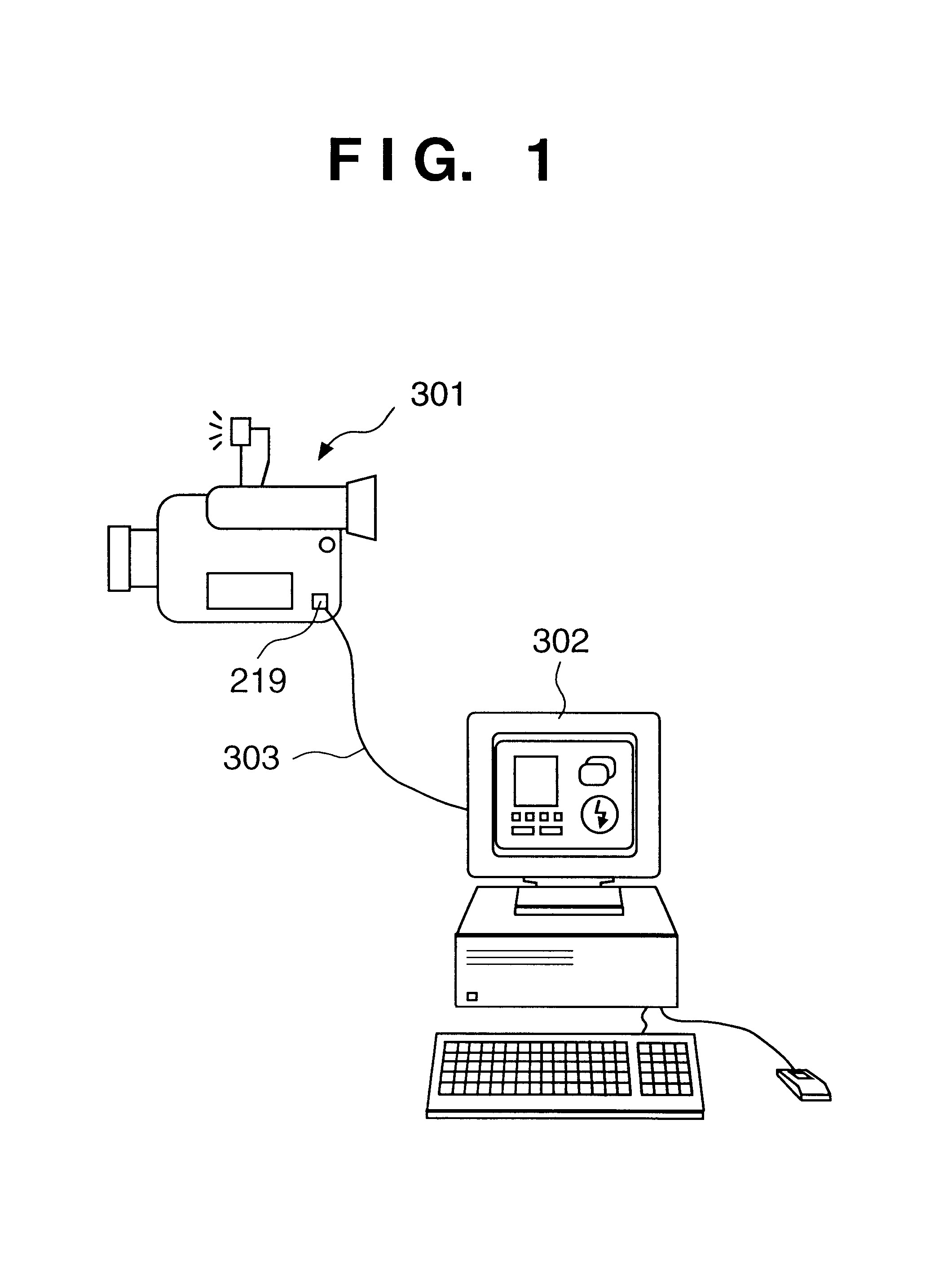
[0080]FIG. 13 is a block diagram illustrating a configuration of an image sensing system according to the present invention;

[0081]FIG. 14 is a diagram showing an effect of camera movements displayed on a display screen;

[0082]FIG. 15 is a flowchart for explaining a sequence of image sensing operation according to the second embodiment of the present invention;

third embodiment

[0083]FIG. 16 is a view showing a control image displayed on a personal computer according to the present invention;

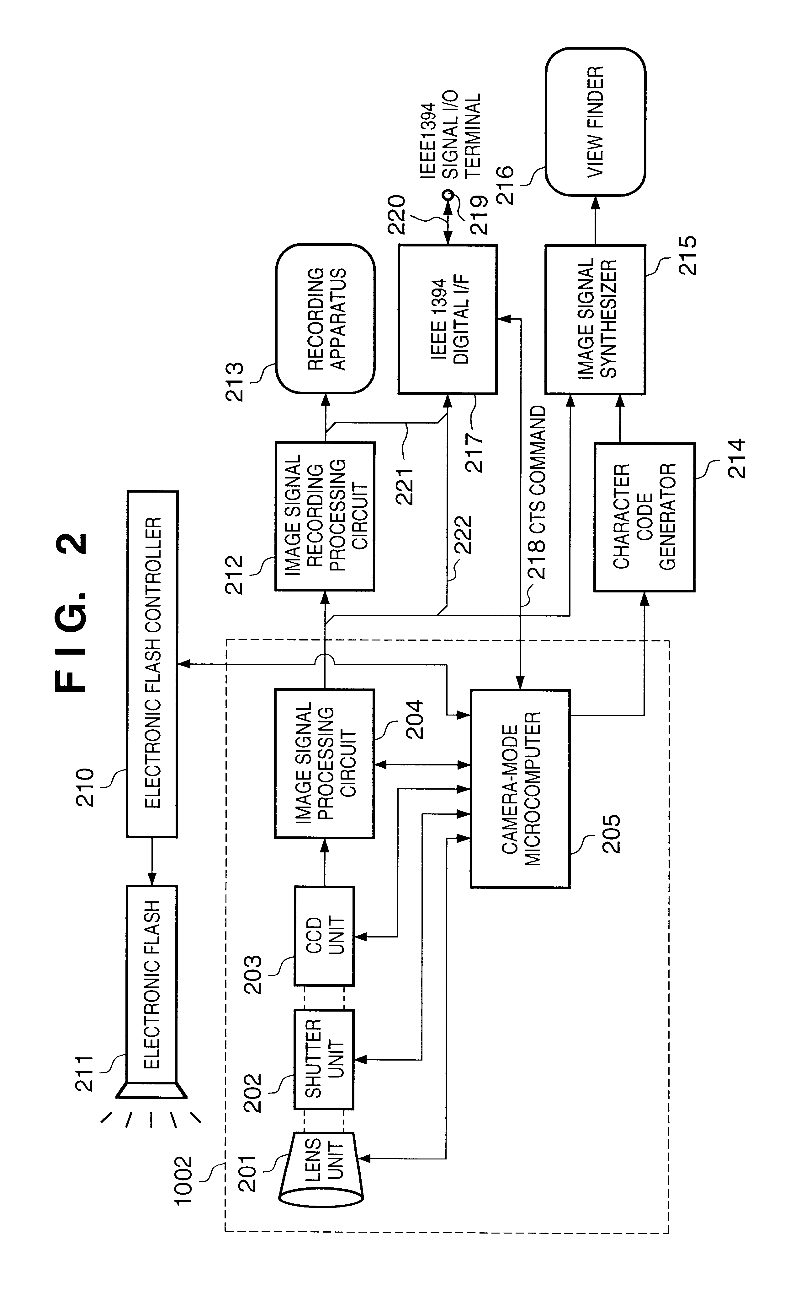
[0084]FIG. 17 is a block diagram illustrating a configuration of an image sensing apparatus according to the third embodiment of the present invention;

fourth embodiment

[0085]FIG. 18 is a block diagram illustrating a configuration of an image sensing apparatus according to the present invention;

[0086]FIG. 19 is a flowchart of a control operation by a control apparatus according to the fourth embodiment of he present invention;


PUM


Abstract

In a method having an image sensor capable of selectively sensing an image in progressive scanning method and in interlace scanning method, when performing an image sensing operation using an electronic flash, if the image sensing operation is performed in the progressive scanning method, the electronic flash is controlled to flash once for each frame, and if the image sensing operation is performed in the interlace scanning method, the electronic flash is controlled to flash twice for each frame, once for each field.

Description

BACKGROUND OF THE INVENTION[0002]The present invention relates to an image sensing system configured with an image sensing apparatus and a control apparatus, a method of controlling an image sensing system, and a storage medium storing the method.[0003]As conventional video cameras, on the market, which record an image as television signals, there are analog video cameras (e.g., HI-8 type, VHS type) and digital video cameras (e.g., DV type).[0004]In these video cameras, a charge coupled device (CCD) is often used as an image sensing device. Referring to FIG. 23A, in the conventional video cameras, in order to output a moving image as television signals, the CCD is scanned every other scan line as shown by interlace scanning lines 602 to form a first field image 601, then the skipped lines are scanned as shown by interlace scan lines 604 to form a second field image 602. The first and second field images 601 and 602 together form a frame image (interlace scanning).[0005]In the afores...

Claims


Application Information

Patent Timeline
IPC IPC(8): H04N5/222H04N5/232H04N5/235
CPCH04N5/23203H04N5/23222H04N5/2354H04N5/23245H04N5/23296H04N5/23225H04N23/66H04N23/617H04N23/64H04N23/667H04N23/69H04N23/74
Inventor MAKINO, JUNKOYAMA, SHINICHITAKEUCHI, YOSHITAKA
Owner CANON KK
Why Eureka
Try Eureka