Memory cement bond logging apparatus and method

a cement bonding and cement technology, applied in the field of oil and gas well exploration tools, can solve the problems of unattenuated casing signal, inability to bond parts of cement columns to casings or formations, and undesirable fluid communication between adjacent porous zones

Inactive Publication Date: 2005-02-01
PROBE TECH SERVICES
View PDF15 Cites 71 Cited by
  • Summary
  • Abstract
  • Description
  • Claims
  • Application Information

AI Technical Summary

Problems solved by technology

For various reasons, the cement may fail to completely fill the annulus along the length of the casing resulting in the condition generally known as “channeling.” Additionally, portions of the column of cement may fail to bond to the casing or formations.
Fluid communication between adjacent porous zones is undesirable.
On the other hand, if no bond or a relatively poor bond exists, the casing signal can be expected to be relatively unattenuated.
To this point, such a technique has proved to be impractical primarily due to the large volumes of memory storage required to store the data in question.

Method used


Image

  • Memory cement bond logging apparatus and method
  • Memory cement bond logging apparatus and method
  • Memory cement bond logging apparatus and method

Examples


Embodiment Construction

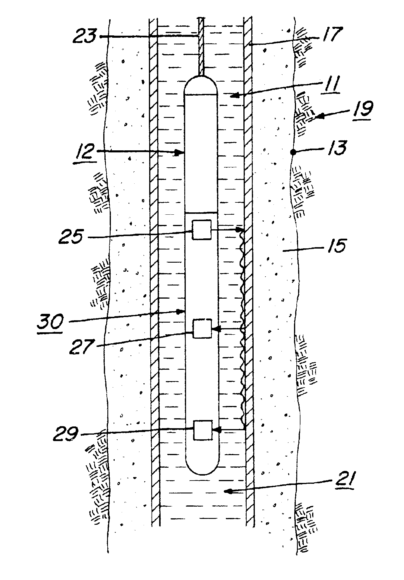
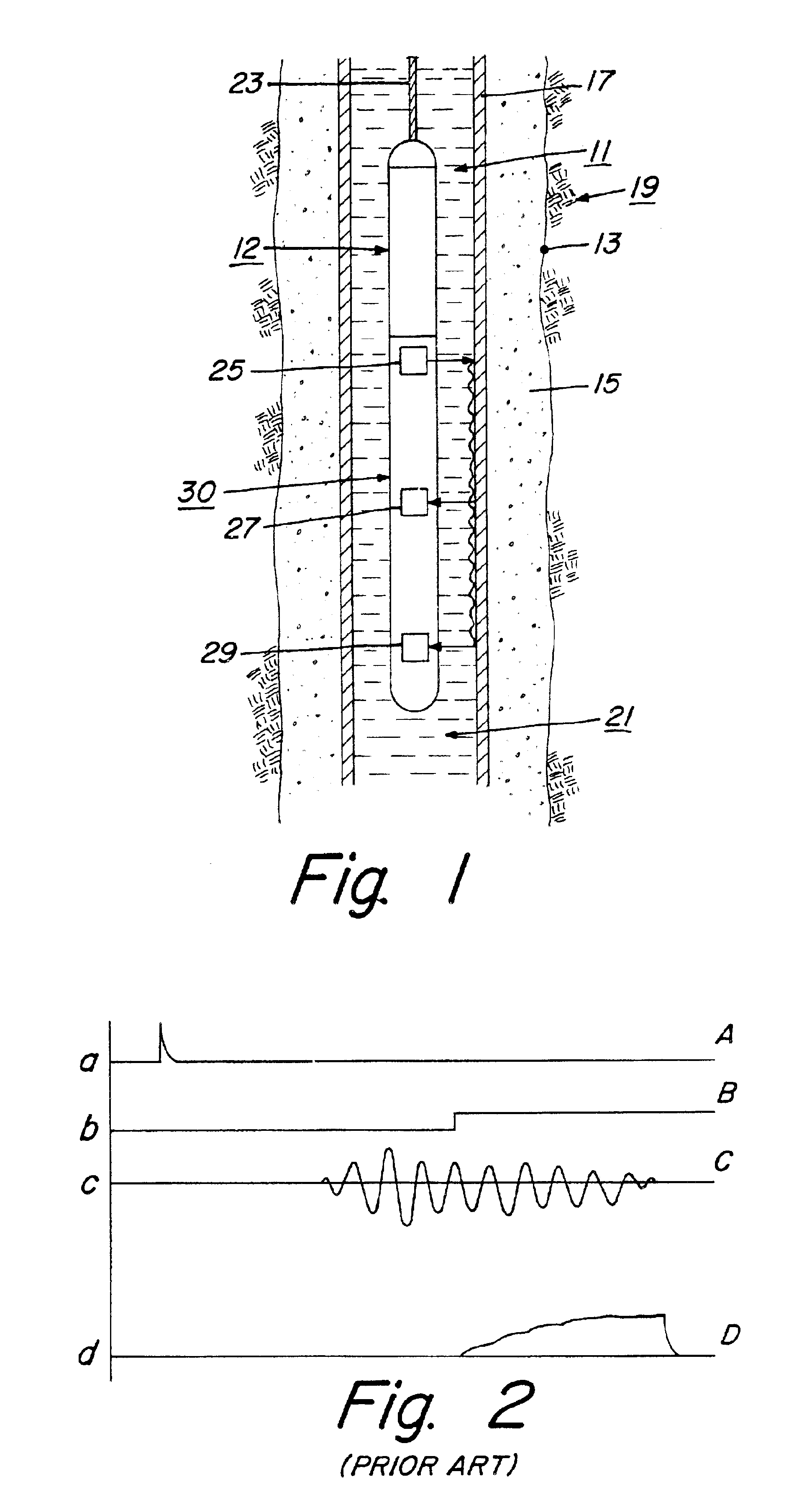
FIG. 1 shows an acoustic logging tool 11 of the invention suspended within a bore hole 13 at a desired depth. As is customary in the art, a cement slurry 15 is pumped into the annular space between the well casing 17 and the surrounding subterranean formation 19. The cement 15 subsequently hardens to form a cement annulus between the casing and formation. In the illustration of FIG. 1, the cement region is seen to be completely bonded to the casing 17 and the surrounding formations 19. The casing interior 21 is filled with a fluid.

The logging tool 11 is of a generally cylindrical shape and is suspended within the casing 17 by means of a conventional slickline 23. By “slickline” is meant a line or cable with no electrical conductor. A suitable winch (not shown) is provided at the well surface for lowering and raising the tool 11 in the bore hole. The tool can be provided with centralizers (not shown) for maintaining it in a concentrically located position within the casing interior.

M...


PUM


Abstract

A method and device are shown for detecting the characteristics of a cement annulus between a casing in a borehole and the surrounding earth formations in a slickline cement bond logging operation. An acoustic logging tool is utilized which produces a pure signal downhole. The received acoustically transmitted energy produces electrical signals indicative of both the amplitude of the received energy and variable density log data. Both the amplitude data and the variable density log data are captured in memory downhole by the use of a time amplitude matrix which stores a limited number of data points for producing a cement bond log at the well surface.

Description

BACKGROUND OF THE INVENTION1. Field of the InventionThe present invention generally relates to exploratory tools for use in oil and gas well bores and, more specifically, to acoustic logging devices and methods used to investigate the acoustic coupling between a well casing and a bore hole.2. Description of the Prior ArtIn a typical well completion operation, a casing for pipe is placed in the bore hole and cement is pumped into the annular region defined between the casing and the surrounding bore hole. For various reasons, the cement may fail to completely fill the annulus along the length of the casing resulting in the condition generally known as “channeling.” Additionally, portions of the column of cement may fail to bond to the casing or formations. In such cases, fluids and / or gases from the formations at various depths may migrate along the imperfections in the column of cement. Fluid communication between adjacent porous zones is undesirable.A number of systems are known in...

Claims


Application Information

Patent Timeline
Patent Type & Authority Patents(United States)
IPC IPC(8): G01V1/44G01V1/40
CPCG01V1/44
Inventor MCDANIEL, RONALD E.SMALL, TONY M.BLOOMFIELD, DWIGHT A.
Owner PROBE TECH SERVICES
Why Eureka
Try Eureka