Device for withdrawing body fluids

a technology for body fluids and devices, applied in the field of medical devices, can solve the problems of paracentesis, formation and rupture of umbilical hernias, respiratory distress, etc., and achieve the effect of minimizing the time of use and losing the vacuum

Active Publication Date: 2006-05-23
DENVER BIOMEDICAL
View PDF10 Cites 78 Cited by
  • Summary
  • Abstract
  • Description
  • Claims
  • Application Information

AI Technical Summary

Benefits of technology

[0023]The risk that the spike accidentally pierces the frangible seal, to lose the vacuum, prior to the time of use can be minimized with appropriate safety devices. In one preferred embodiment, the safety device is a clip that clips over the neck formed by the spike between the bottle mouth and a flange on the drainage line. So long as the clip is in place, any force urging the spike toward the frangible seal is transferred through the clip so that the spike cannot actually reach the frangible seal. At the time of use, the clip is simply removed to allow the spike to pierce the frangible seal in the manner described above.

Problems solved by technology

Typical patients have tense ascites resulting from liver disease and portal hypertension, which may cause discomfort, respiratory distress, and the formation and rupture of umbilical hernias.
Other treatment options, such as the use of diuretics, are available, but may not provide as effective relief as paracentesis.
Additionally, many patients with ascites have renal impairment and cannot use the high doses of diuretics necessary to effectively treat the ascites.
This reduces the likelihood of the sharp needle damaging internal tissue during paracentesis.
Problems may arise when drainage is diverted from one container to another if the drainage system is not airtight.
Air could contaminate a sample or enter the body of the patient and cause injury.
Known devices that are meant to be airtight have tubes and multiple containers attached to the devices which make the devices cumbersome and somewhat difficult to insert into the patient.
If the stopcock is not set at the proper setting, the device may admit air into the patient or otherwise malfunction.
Problems also may arise in devices which allow a needle assembly to be withdrawn.
A disruption in the balance between the movement of fluid into the pleural space and the movement of fluid out of the pleural space may produce excessive fluid accumulation in the pleural space.
Pleural effusion may cause dyspnea, coughing, and chest pain, which diminish a patient's quality of life.
However, pleurectomy is a major surgical procedure associated with substantial morbidity and some mortality.
Chemotherapy is generally disappointing; however, it may produce good responses for patients with lymphoma, breast cancer, or small-cell carcinoma.
However, such a tube is painful to the patient, both when it is inserted and during the time that it remains in the pleural space.
However, thoracentesis poses the danger of causing pneumothorax, a collapsed lung.
If the atmosphere is allowed to communicate with the pleural space, the pleural space may no longer be at negative pressure and pneumothorax may result.
However, none of the previous devices allow for a truly fail-safe operation, as various valves must be properly set by the operator when changing from one drain port to another or when withdrawing the introducing needle assembly from the patient.
Due to the possibly dire consequences of a valve failure, such valves may not produce acceptably safe thoracentesis.
While this reduces the risk of pneumothorax due to lung puncture, the Turkel device does not improve the safety of thoracentesis when the introducing needle assembly is withdrawn or solve the problems associated with multiple drainage ports.
Other difficulties with existing systems relate to manufacturing, storing and using the vacuum element.
Syringes are sometimes used to generate the vacuum, but syringes are somewhat complicated to manufacture and use.
This is quite ingenious in concept but somewhat difficult to implement.
There is always some risk that the vacuum will be lost in transit before use, either by leaks, fractures or just air permeating through a plastic wall.
Moreover, the loss of vacuum is not necessarily apparent to the user; a bottle with a perfect vacuum inside looks no different than a bottle of air.
Another problems is in tapping the bottle.
This requires a system that pierces a vacuum seal but does not allow air to enter the bottle, except through the draw line.

Method used


Image

  • Device for withdrawing body fluids
  • Device for withdrawing body fluids
  • Device for withdrawing body fluids

Examples


Embodiment Construction

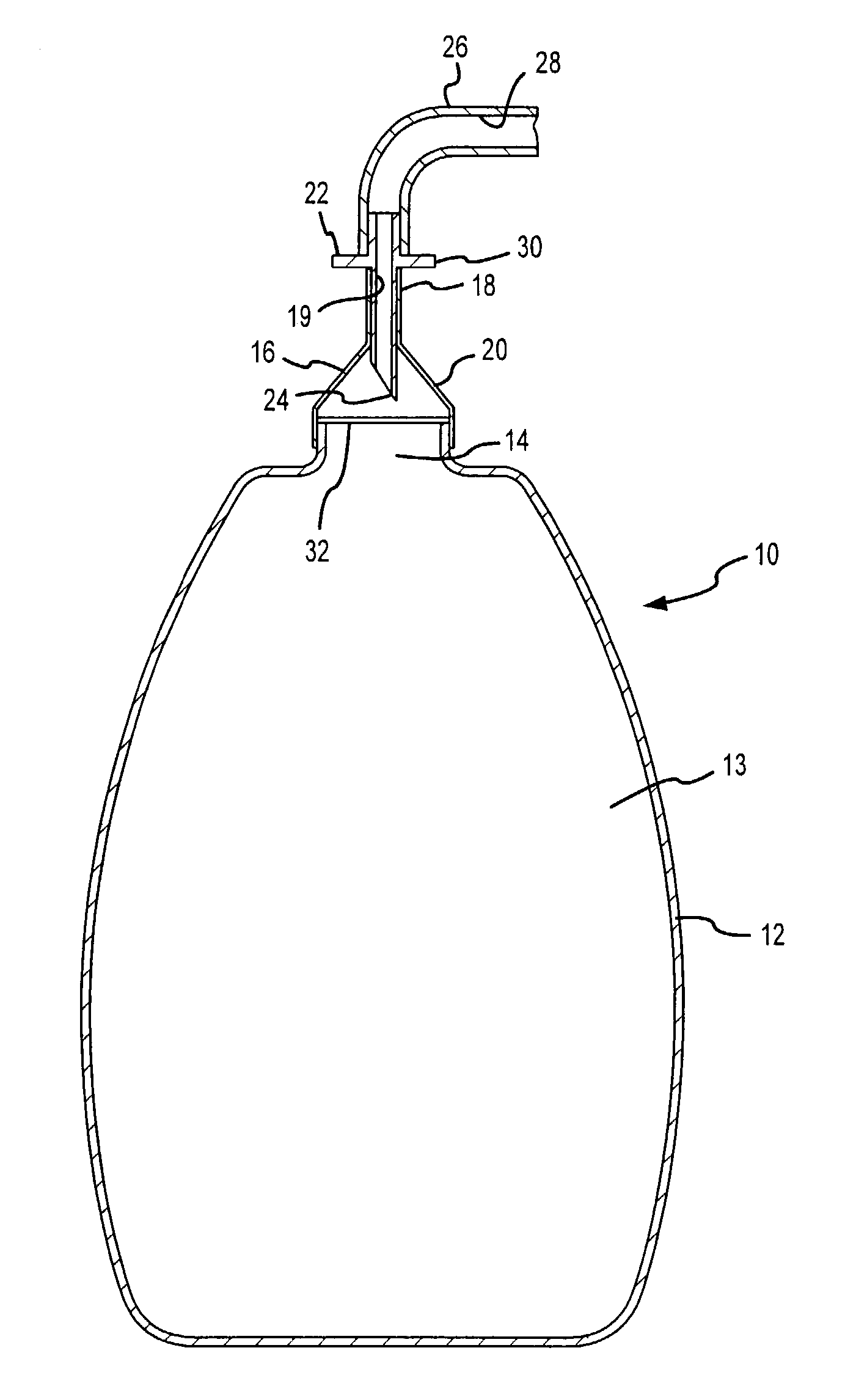
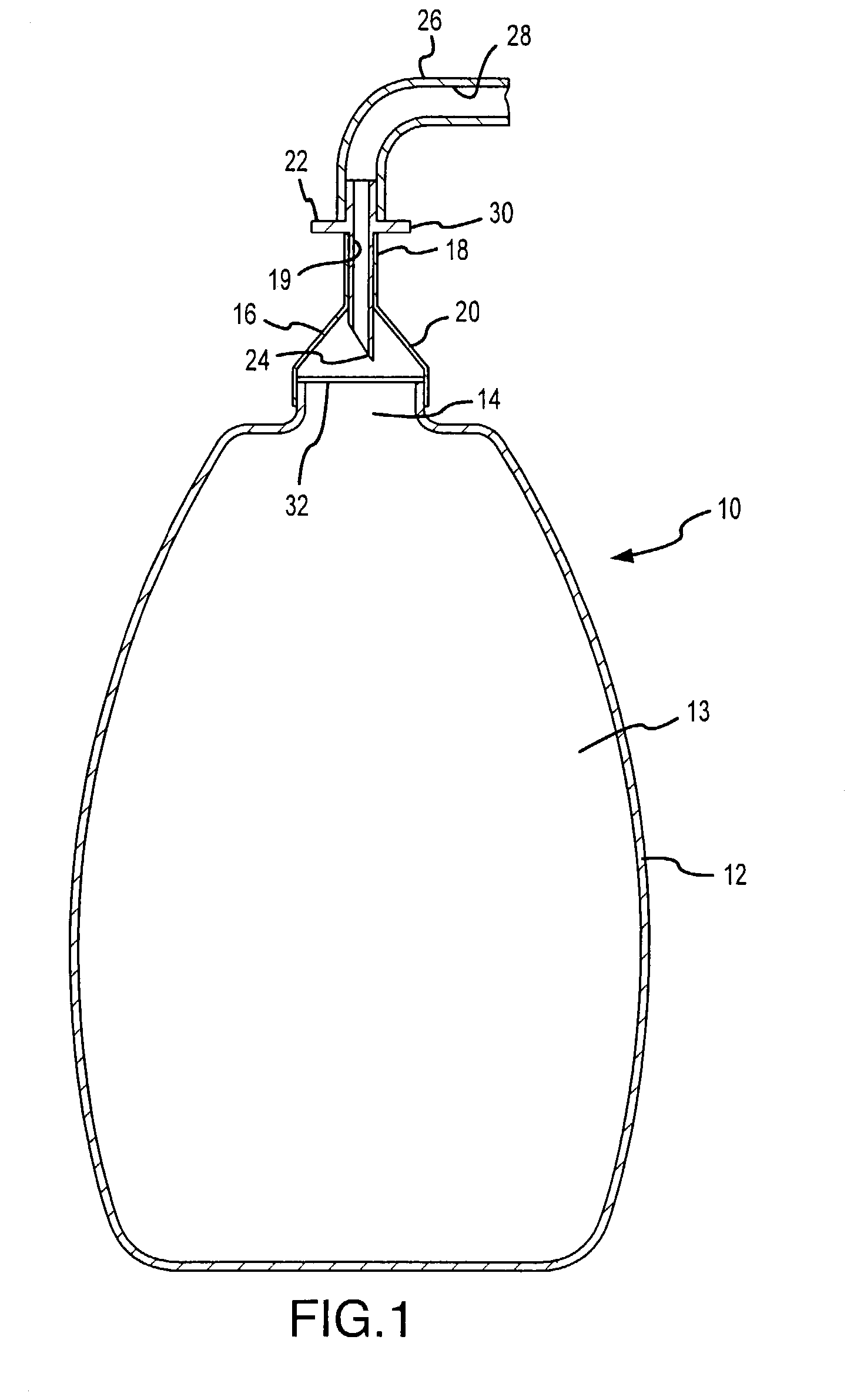
[0031]FIG. 1 shows a preferred embodiment of the invention 10 in a partial sectional view. The invention includes a bottle 12 having a mouth area 14. Covering the mouth area 14 is an elastomeric cap 16 having a sleeve 18 at the upper end and a widened body 20 at the lower end. The sleeve 18 of the elastomeric cap 16 receives a spike 22 in a substantially air tight seal between the spike 22 exterior surface and the lumen of the sleeve 18.

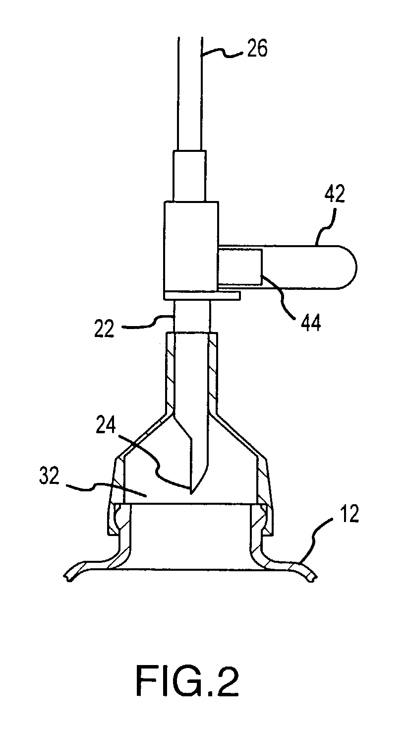
[0032]The lower end of the spike 22 terminates in a point 24. The upper end of the spike 22 receives a drainage line 26 having a lumen 28 therethrough. As in the connection between the spike 22 and the sleeve 18 of the elastomeric cap 16, this connection between the spike 22 and the drainage line 26 is preferably substantially air-tight. The spike 22 may also include a circumferential flange 30 to assist in manipulating the spike 22 in relation to the bottle 12 in the manner described below. Extending through the spike 22 is a spike lumen 19.

[0033]Se...


PUM


Abstract

An apparatus and method for draining fluid from a patient. A drainage line is connected to a vacuum bottle. The vacuum is transferred into the drainage line by piercing a seal over the bottle mouth. The indicator in the form of a collapsible bulb or other deformable element confirms the presence of the vacuum at the time of use.

Description

FIELD OF THE INVENTION[0001]The present invention relates to the field of medical devices and, in particular, to a device useful for withdrawing body fluids in procedures such as paracentesis and thoracentesis.BACKGROUND[0002]Body fluids may need to be withdrawn from a patient in the course of medical treatment. Two common medical procedures requiring fluid removal are thoracentesis and paracentesis.[0003]In paracentesis, peritoneal fluid is aspirated from the abdomen. Typical patients have tense ascites resulting from liver disease and portal hypertension, which may cause discomfort, respiratory distress, and the formation and rupture of umbilical hernias. Paracentesis has been observed to provide quick and effective relief with few adverse side effects. Other treatment options, such as the use of diuretics, are available, but may not provide as effective relief as paracentesis. Additionally, many patients with ascites have renal impairment and cannot use the high doses of diuretic...

Claims


Application Information

Patent Timeline
Patent Type & Authority Patents(United States)
IPC IPC(8): A61M1/00
CPCA61M1/0003A61M1/732A61M1/63A61M1/66
Inventor GROSSMAN, PHILLIPERICKSON, WARRENBUREK, PAULVIVIAN, BONNIE
Owner DENVER BIOMEDICAL
Why Eureka
Try Eureka